Project 2 – Modeler
Due: Tuesday Apr 19 11:00am (before class)
- Overview
- Getting Started
- Requirements
- Surface of Revolution
- Hierarchical Modeling
- Augmented Reality
- Turn In
Overview
3D modeling is a key part of the computer graphics and animation pipeline. This is typically performed using industrial-strength tools like Maya, 3DS Max, and Blender. These models can be imported to a 3D engine like Unity to create interactions and behaviors that suit your application needs.
There are three parts to this project. First, you will use the surface of revolution technique to construct a mesh with radial symmetry. Second, you will compose several geometric primitives using proper hierarchy and transformations to achieve a humanoid model which you will then create several animation loops for it. Finally, you will visualize your model and its animations in a virtual environment inside your mobile device. This is also known as augmented reality (AR).
Getting Started
Clone the modeler-skeleton repository. From Unity Hub, open the cloned folder. There will be three scenes corresponding to three parts of the project: SurfaceOfRevolution, HierarchicalModeling, and ARScene.
Help Slides Sample Solution (Windows) Sample Solution (Mac)
Requirements
Surface of Revolution
Implement the surface of revolution in CreateMeshData() in SurfaceOfRevolution.cs. You will compute the position, normal, and texture coordinate for each vertex. The mesh must have correct connectivity (correct vertex orientation and no unnecessary vertices), and you must comply with the number of radial subdivisions.
Hierarchical Modeling
You will create a humanoid-like model using simple meshes (like cube, sphere, cylinder, etc.) and at least one surface revolution component you made in the previous part. You will need to create an appropriate hierarchy for your component that would allow for reasonable manipulation and transformation of the parts. Lastly, implement at least two basic animations.
AR Application
There is no coding required in this part. Instead, you must import your hierarchical model to the AR Modeler Project; and build the application on your mobile device, open the app, and capture an image of it in a real-life scene. (preferably with you in it).
Surface of Revolution
A surface of revolution is a surface created by rotating a curve around an axis. The interface for editing the curve is already provided. Your task is to implement the surface of revolution algorithm given the samples of points on the curve and the number of radial subdivisions. Typically, to describe a mesh you only need vertex positions and a triangle list of how the vertices are connected. In this project however, you are required to compute the vertex normal and the texture coordinate (UV coordinates) for each vertex.
Program Overview
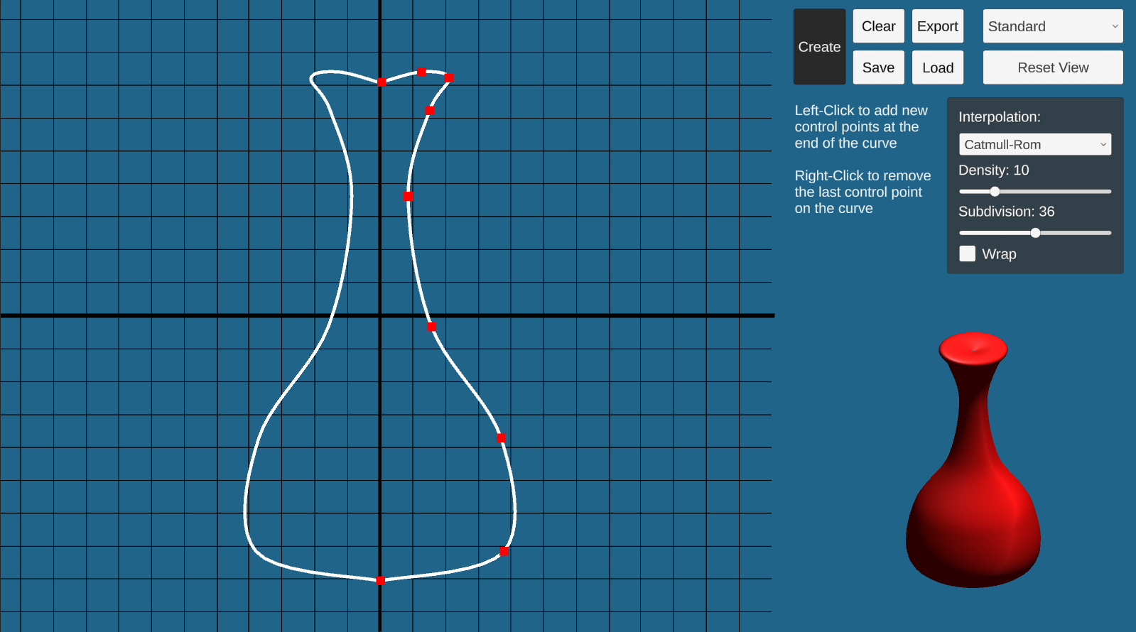
Go to the SurfaceOfRevolution scene and hit play. In “Play” mode, you will see a working curve editor on your left and some options on the top-right. You should change the resolution to Full HD or any with 16:9 aspect ratio for the UI to display correctly. Right now, you can only create and delete control points of the curve. Once your code is done, you will be able to click ‘Create’ and the output mesh will appear on the lower-right of the screen.
To construct a curve, click anywhere on the graph. The control point will appear on the screen. This graph is on the xy-plane, and the curve you created will be automatically reflected with respect to the y-axis for visualization purposes.
There are several options for the curve and the output mesh:
- Interpolation: determines the interpolation method between adjacent control points. Two options provided are: Catmull-Rom (smooth), and Linear. Note that for the Catmull-Rom option, you will need at least 4 control points whereas the linear option needs at least two.
- Density: the number of samples between two adjacent control points. More density means the curve will look smoother.
- Subdivision: the number of radial subdivisions. This is the option passed to your function. More subdivisions means the mesh will look smoother around the vertical axis.
- Wrap: whether to close the curve (basically, to connect the last control point to the first)
After changing these options, you will need to click Create again for the change to reflect on your output mesh. We suggest you use the default settings while you are trying to debug your code.
We provide four viewing options of the output mesh (top-right dropdown) to aid your debugging: standard, wireframe, normal visualization, and textured. You can use the wireframe to see the actual triangle of your mesh. The normal visualization shows different colors based on the direction of the normal at that point. This mode is helpful to determine if you get the vertex normals correct. The textured shows your mesh with the textured material. This will help determine if you get your UV coordinates right.
Once you have created a surface, you can click Save to save the control points to a text file, and you can use Load to load that text file back to get the exact same control points. You can also Export the model as a .asset file so that it can be used in the next part of the project or one of your own.
Surface of Revolution Implementation
To complete this part, fill out the ComputeMeshData() function in the SurfaceOfRevolution.cs.
Your function will use the following variables as inputs:
curvePoints: the list of sampled points on the curvesubdivisions: the number of radial subdivisions
Your function will compute the following, which will be used to generate and visualize the output mesh:
vertices: a list ofVector3containing the vertex positionsnormals: a list ofVector3containing the vertex normals. The normal should be pointing out of the mesh.UVs: a list ofVector2containing the texture coordinates of each vertextriangles: an integer array containing vertex indices (of theverticeslist). The first three elements describe the first triangle, the fourth to sixth elements describe the second triangle, and so on. The vertex must be oriented counterclockwise when viewed from the outside.
Note that since vertices, normals, UVs are per-vertex information, they will have the same size: the number of vertices.
Texture mapping allows you to “wrap” an image around your model by mapping points on the texture to the vertices of your model. For each vertex, you indicate the coordinate in the texture space that the vertex should be mapped to as a 2D pair (U, V) where U and V range from 0 to 1. For example, if the UV coordinates of vertex 8 is (0.5, 0.5), The very center pixel of the texture will be mapped to vertex 8. Unity and the shader will automatically interpolate the UV coordinate inside the faces based on the UV coordinate of the vertices.
We recommend you first start working on computing the vertices and triangles. Then, move on to normals, and lastly the UVs.
Using Different Textures
If you want to use a different texture, you will need to do the following:
- Import an image file into your scene by drag-and-dropping the image into the Assets folders under the Project tab.
- Select Assets/Resources/TexturedMat material, then navigate to the Inspector pane to set its Albedo property under Main Maps to be the image file.
Verifying your Implementation
To verify the correctness of your implementation, follow these steps:
- Select Load, then navigate to the
ControlPointsfolder and choose our provided filesample1.txt,sample2.txt, etc. - After the points are loaded, click Create to draw a surface of revolution.
- Do the same for the solution program. Observe if the output from your implementation is similar to the solution. Change to a different viewing mode and then compare your results with the solution.
Hierarchical Modeling
In this part, you will create a basic humanoid model and add simple animations. The provided HierarchicalModel scene, which is basically empty, is the place for you to compose the model.
The Model
Regarding your hierarchical model, there are 2 requirements:
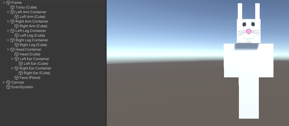
- The model must be a humanoid whose hierarchy tree has a minimum depth of 3. Your model is created by a hierarchy of nodes, including empty nodes and Shape nodes (Cube, Sphere, Cylinder, etc). Below is a basic humanoid model which is created with Cube GameObjects.
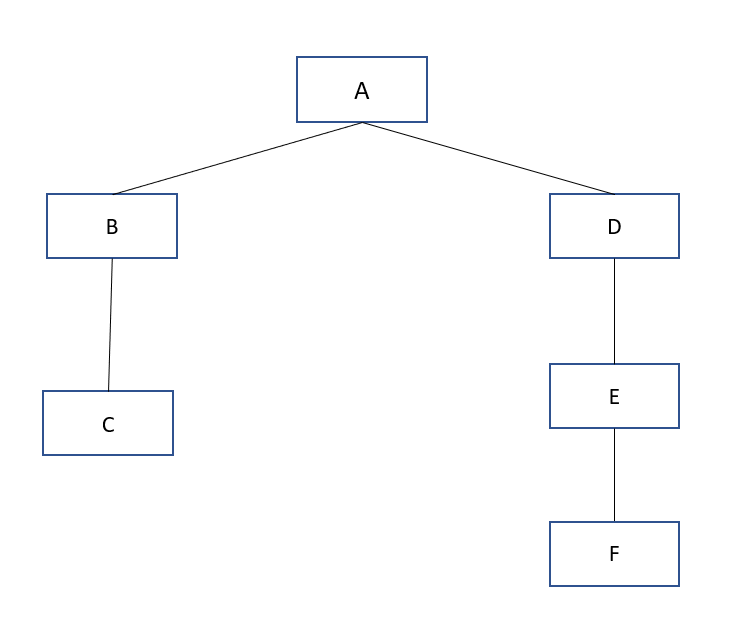
Here’s an example of a tree with the minimum depth of 3. Your hierarchical model, which consists of Empty Nodes and Shape (Cube, Sphere, Cylinder, etc.) nodes, should be at least as deep as this.
- The model must have at least one component made of your created surface of revolution. After creating your surface of revolution, click Export to save it as a .asset file. Then, in the HierarchicalModel scene, right-click anywhere in the Assets tab and choose Import new asset and select the file that you just saved. The surface is imported, which can be dragged into your Scene or converted into a Prefab. As an example, your model’s arms or other body parts could be made of this surface.
We recommend you refer to class lectures and write down the tree diagram of your model to help you figure out what your model will be, and to practice thinking about empty nodes, centers of rotation, and so on. You do not need to turn in your diagram.
In addition to providing a little fun, the animations will help you learn more about hierarchy design – you will find that certain animations are easier if you plan your hierarchy together with the animations you want to perform.
The Animations
You are to create 3 buttons that execute basic animations for your model as follows:
- Button 1: Rotate the entire model in a circle
- Button 2: Implement a walking animation for your model.
- Button 3: Implement animation of your choice. Below is an example of what these buttons might do. Be creative :-)
Please refer to the MazeGame project on how to create buttons. You will need to add a script to your model and apply some transformation changes.
Below is a small example to get the Transform object of each component.
public GameObject body; // assigned through Inspector pane
Transform bodyInner = body.transform.Find(“BodyInner”);
Transform head = bodyInner.Find(“Head”);
Transform leftArm = bodyInner.Find(“LeftArm”);
To set the transformations: (to be called every FixedUpdate call)
leftArm.rotation = Quarternion.Euler(0.5, 0, 0);
head.localPosition = new Vector3(1, 2, 3);
head.localScale = new Vector3(1, 1.5, 1);
Augmented Reality
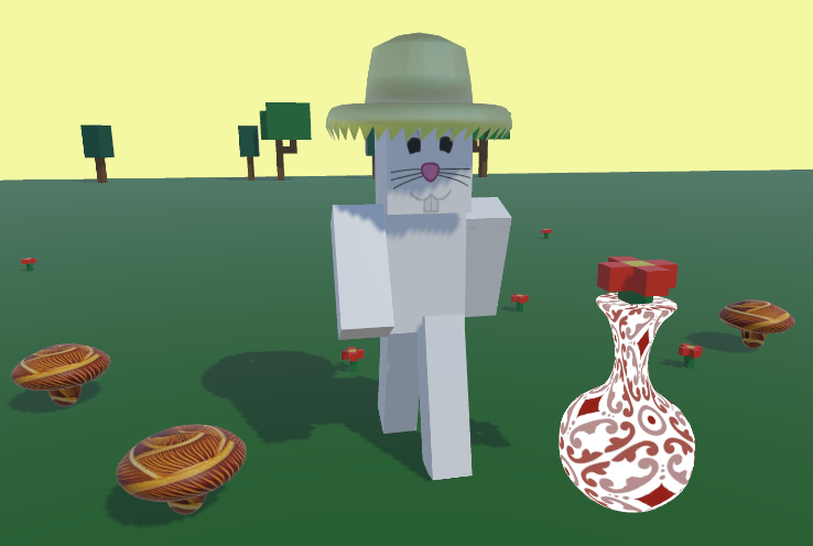
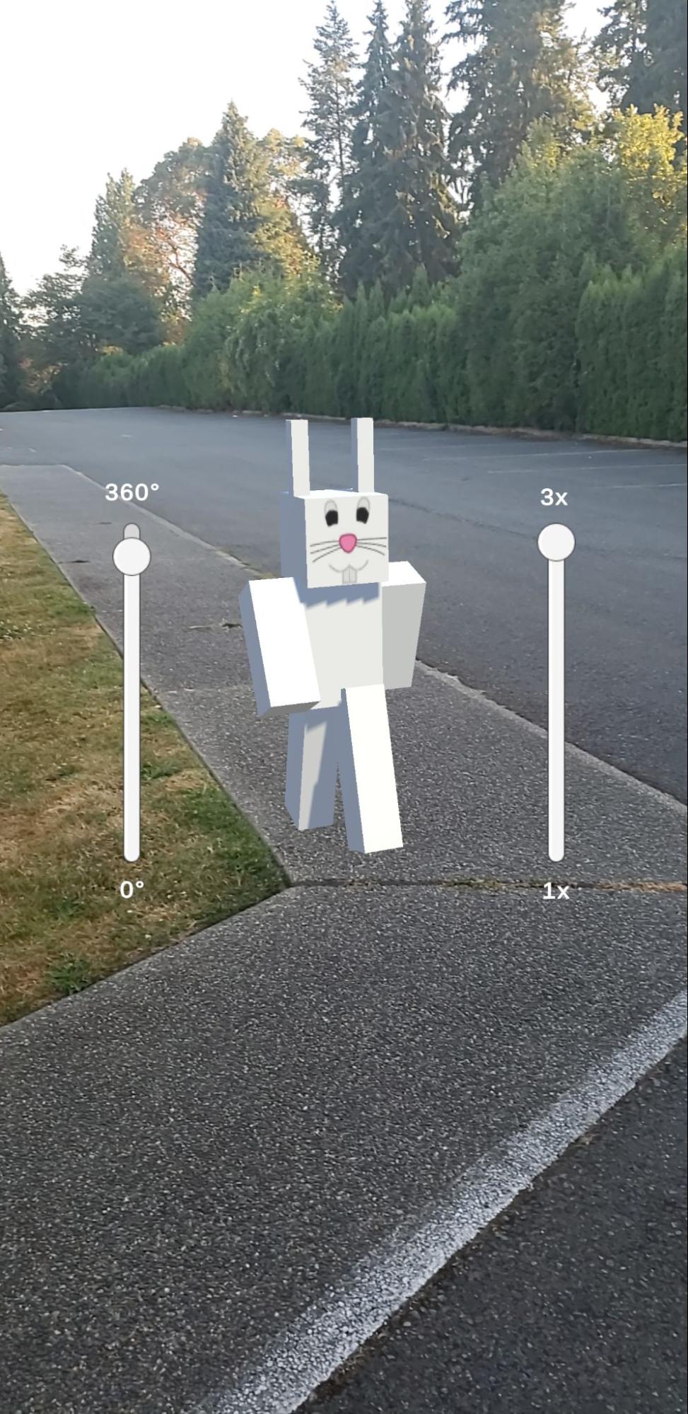
In this part, you will project your model into the real world using ARCore and your mobile phone! If you don’t have a compatible phone, you can check out one of our lab devices. This is what it will look like view your artifact in AR:
Follow these steps to turn your artifact into an AR object.
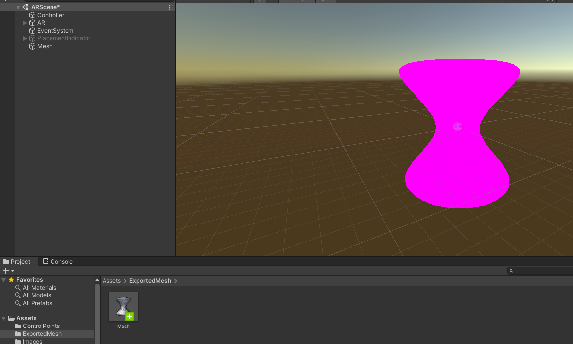
- Export your mesh: after creating your surface of revolution. Click on the Export button to save your mesh in the
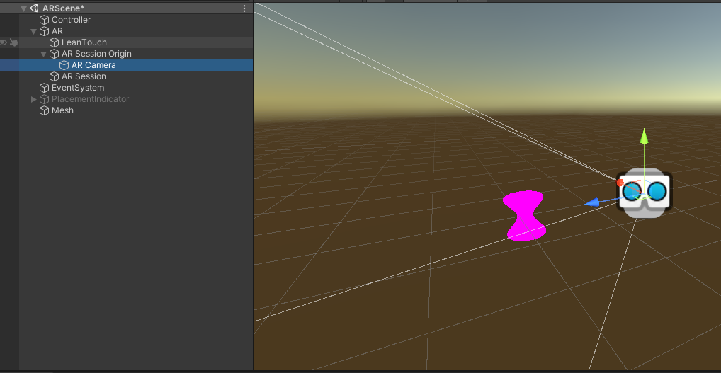
Assets/ExportedMeshfolder. - Open the ARScene scene and drag the exported mesh into the hierarchy like this:
- Scale the mesh down so that it is fully captured by the AR Camera. Now, you can assign any material to the mesh.
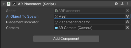
- Select the Controller GameObject from the hierarchy and set the AR Object To Spawn to the mesh.
- Go to File → Build Settings and select between Android/iOS to build and run the AR scene on your mobile device. Refer to the MazeGame project on how to build the application to either Android or iOS devices.
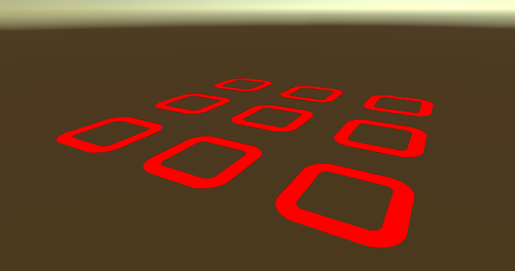
- When the application is making use of your device’s camera, point the camera around your surroundings, wait until a red placement indicator appears and tap on it to spawn your mesh. You can drag the mesh around using 1 finger, or scale and rotate it using 2 fingers.
If you are using iOS, you might have to turn off your iWatch.
Turn In
You will record a short video (~4 minutes) demonstrating you have completed the requirements.
- (~2 minutes) Screen recording of your surface of revolution scene. Load and create the mesh from the sample curves (sample1 to sample5). For each sample, you will select different viewing modes (there are 4), and for each viewing mode, rotate the mesh around (left and right, up and down) so we can see the whole mesh.
- (~1 minute) Screen recording of your hierarchical model scene. Make sure the entire model and the Hierarchy pane are visible in your recording.
- (~30 seconds) Expand all entries that you created in the Hierarchy pane. Click on each entry. The selected entry should be highlighted. Iterate through all entries you created.
- (~30 seconds) Click each button you created and record the animation.
- (~1 minute) Ask someone to record you interacting with the model in the AR app on your phone. Set up a screen recorder on your phone and ask someone to point your phone towards you. Basically, you will be inside the AR world with your model.
Submit your video as a .mp4 file on Canvas by the due date.