Project 2: Modeler


Assigned Jan 26, 2023
Due Feb 10, 2023
Artifact Due Feb 12, 2023
Help Sessions Sign up for Office Hours with Ethan
Project TA Ethan Vrhel
Artifact Turn-in
Artifact Winners Winners

Overview


Description

3D modeling is a key part of the computer graphics and animation pipeline. This is typically performed using industrial-strength tools like Maya, 3DS Max, and Blender. These models can be imported to a 3D engine like Unity to create interactions and behaviors that suit your application needs. 
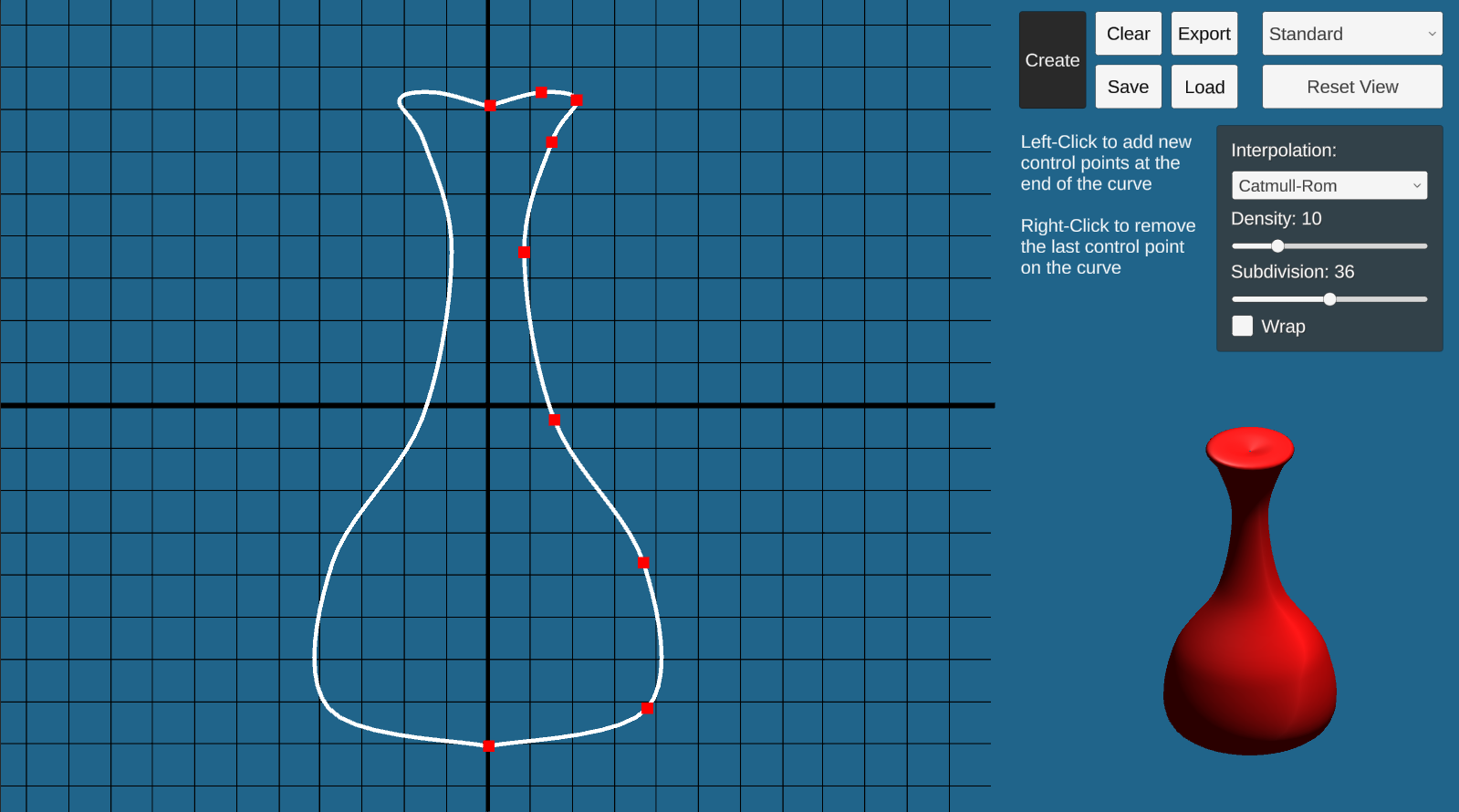
There are three parts to this project. First, you will use the surface of revolution technique to construct a mesh with radial symmetry. 
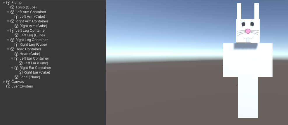
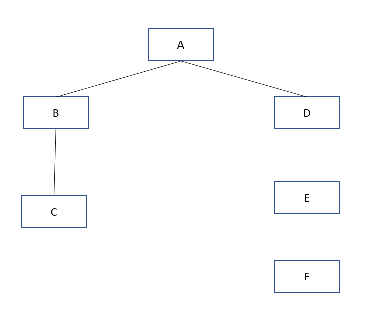
Second, you will compose several geometric primitives using proper hierarchy and transformations to achieve a humanoid model which you will then create several animation loops for it.

Getting Started

You will need to install Unity to work on this project. For instructions on how to install Unity and Unity Hub, see the help page. To open the project, first clone the skeleton code, open Unity Hub, click the Open button and navigate to your cloned repository. Open the folder that contains the README.md file inside it. It may take a while the first time opening to import all the necessary packages.

The skeleton code is also avaliable here.

A brief tutorial of Unity is avaliable on the help page.

Requirements


Implement the surface of revolution in ComputeMeshData() in SurfaceOfRevolution.cs. You will compute the position, normal, and texture coordinate for each vertex. The mesh must have correct connectivity (correct vertex orientation and no unnecessary vertices), and you must comply with the number of radial subdivisions.

Surface of Revolution


A surface of revolution is a surface created by rotating a curve around an axis. The interface for editing the curve is already provided. Your task is to implement the surface of revolution algorithm given the samples of points on the curve and the number of radial subdivisions. Typically, to describe a mesh you only need vertex positions and a triangle list of how the vertices are connected. In this project however, you are also required to compute the vertex normal and the texture coordinate (UV coordinates) for each vertex.

Program Overview

Go to the SurfaceOfRevolution scene and hit play. In “Play” mode, you will see a working curve editor on your left and some options on the top-right. You should change the resolution to Full HD or any with 16:9 aspect ratio for the UI to display correctly. Right now, you can only create and delete control points of the curve. Once your code is done, you will be able to click ‘Create’ and the output mesh will appear on the lower-right of the screen.

To construct a curve, click anywhere on the graph. The control point will appear on the screen. This graph is on the xy-plane, and the curve you created will be automatically reflected with respect to the y-axis for visualization purposes.

There are several options for the curve and the output mesh:

  • Interpolation: determines the interpolation method between adjacent control points. Two options provided are: Catmull-Rom (smooth), and Linear. Note that for the Catmull-Rom option, you will need at least 4 control points whereas the linear option needs at least two.
  • Density: the number of samples between two adjacent control points. More density means the curve will look smoother.
  • Subdivision: the number of radial subdivisions. This is the option passed to your function. More subdivisions means the mesh will look smoother around the vertical axis.
  • Wrap: whether to close the curve (basically, to connect the last control point to the first)

After changing these options, you will need to click Create again for the change to reflect on your output mesh. We suggest you use the default settings while you are trying to debug your code.

We provide four viewing options of the output mesh (top-right dropdown) to aid your debugging: standard, wireframe, normal visualization, and textured. You can use the wireframe to see the actual triangle of your mesh. The normal visualization shows different colors based on the direction of the normal at that point. This mode is helpful to determine if you get the vertex normals correct. The textured shows your mesh with the textured material. This will help determine if you get your UV coordinates right.

Once you have created a surface, you can click Save to save the control points to a text file, and you can use Load to load that text file back to get the exact same control points. You can also Export the model as a .asset file so that it can be used in the next part of the project or one of your own.

Surface of Revolution Implementation

To complete this part, fill out the ComputeMeshData() function in the SurfaceOfRevolution.cs.

Your function will use the following variables as inputs:

  • curvePoints: the list of sampled points on the curve
  • subdivisions: the number of radial subdivisions

Your function will compute the following, which will be used to generate and visualize the output mesh:

  • vertices: a list of Vector3 containing the vertex positions.
  • normals: a list of Vector3 containing the vertex normals. The normal should be pointing out of the mesh.
  • UVs: a list of Vector2 containing the texture coordinates of each vertex
  • triangles: an integer array containing vertex indices (of the vertices list). The first three elements describe the first triangle, the fourth to sixth elements describe the second triangle, and so on. The vertex must be oriented counterclockwise when viewed from the outside.

Note that since vertices, normals, UVs are per-vertex information, they will have the same size: the number of vertices.

Texture mapping allows you to “wrap” an image around your model by mapping points on the texture to the vertices of your model. For each vertex, you indicate the coordinate in the texture space that the vertex should be mapped to as a 2D pair (U, V) where U and V range from 0 to 1. For example, if the UV coordinates of vertex 8 is (0.5, 0.5), The very center pixel of the texture will be mapped to vertex 8. Unity and the shader will automatically interpolate the UV coordinate inside the faces based on the UV coordinate of the vertices. You may create a copy of the first set of vertices to allow the UVs to map to the entire texture.

We recommend you first start working on computing the vertices and triangles. Then, move on to normals, and lastly the UVs.

Using Different Textures

If you want to use a different texture, you will need to do the following:

  1. Import an image file into your scene by drag-and-dropping the image into the Assets folders under the Project tab.
  2. Select Assets/Resources/TexturedMat material, then navigate to the Inspector pane to set its Albedo property under Main Maps to be the image file.

Using Different Textures

To verify the correctness of your implementation, follow these steps:

  1. Select Load, then navigate to the ControlPoints folder and choose our provided file sample1.txt, sample2.txt, etc.
  2. After the points are loaded, click Create to draw a surface of revolution.
  3. Do the same for the solution program. Observe if the output from your implementation is similar to the solution. Change to a different viewing mode and then compare your results with the solution.

Hierarchical Modeling


In this part, you will create a basic humanoid model and add simple animations. The provided HierarchicalModel scene, which is basically empty, is the place for you to compose the model.

The Model

Regarding your hierarchical model, there are 2 requirements:

  • The model must be a humanoid whose hierarchy tree has a minimum depth of 3. Your model is created by a hierarchy of nodes, including empty nodes and Shape nodes (Cube, Sphere, Cylinder, etc). Below is a basic humanoid model which is created with Cube GameObjects.

    Here’s an example of a tree with the minimum depth of 3. Your hierarchical model, which consists of Empty Nodes and Shape (Cube, Sphere, Cylinder, etc.) nodes, should be at least as deep as this.

  • The model must have at least one component made of your created surface of revolution. After creating your surface of revolution, click on the Export button to save your mesh in the Assets/ExportedMesh folder. Then, in the HierarchicalModel scene, right-click anywhere in the Assets tab and choose Import new asset and select the file that you just saved. The surface is imported, which can be dragged into your Scene or converted into a Prefab. As an example, your model’s arms or other body parts could be made of this surface.

We recommend you refer to class lectures and write down the tree diagram of your model to help you figure out what your model will be, and to practice thinking about empty nodes, centers of rotation, and so on. You do not need to turn in your diagram.

In addition to providing a little fun, the animations will help you learn more about hierarchy design – you will find that certain animations are easier if you plan your hierarchy together with the animations you want to perform.

The Animations

You are to create 3 buttons that execute basic animations for your model as follows:

  • Button 1: Rotate the entire model in a circle
  • Button 2: Implement a walking animation for your model.
  • Button 3: Implement animation of your choice. Below is an example of what these buttons might do. Be creative :-)

You will need to create a new script and attach it to your model to manage animations and handle when the user presses a button. Create a Canvas GameObject to create a UI (UI -> Canvas). Add buttons by creating a Button GameObject (UI -> Button - Text Mesh Pro). Make sure your buttons are child GameObjects of your Canvas.

Rotations are stored as a Quaternion. To convert between euler angles and quaternions, use the Quaternion.Euler() method to create quaternions, and the eulerAngles property of a Quaternion instance to retrieve the euler angles of a quaternion. If you want to interpolate between quaternions, use Quaternion.Slerp(), which perfoms spherical linear interpolation. You may also use Vector3.Lerp() to linearly interpolate between euler angles and then convert to a quaternion.

You will want your animations to be the same speed regardless of framerate, so you should make use of Time.deltaTime (which gives the amount of time that has passed since the previous frame) to normalize the animation speed. You may also place your animation code in FixedUpdate() which has a fixed Time.deltaTime.

Do not use Unity's built in animation features. You should manually create the animations through scripting.

Turn-in Information


Please follow the general instructions here.

Artifact Submission

For the artifact, you will be submitting a screen recording of you demonstrating your hierarchical model. This can include things such as your animations or showcasing any bells and whistles you implemented on the hierarchical model. You should turn in a short video screencapture (.MP4 format no longer than 30 seconds) and a screenshot of your model to go with it. You can use any screen recording software you like, one such program is Open Broadcaster.

Bells and Whistles


You should implement at least one bell and one whistle. Record which ones you implemented in the README.md file in your repository. Many of these require controllable sliders to dynamically change your model. Unity has a built-in slider under UI -> Slider.

Lighting

Create a controllable light source to illuminate your model. It should be controllable by a slider (perhaps by changing its position or color).

Camera Animation

Animate the camera alongside your model. There are more complex implementations you can do below.

Your Own Whistle

Come up with another whistle and implement it. A whistle is something that extends the use of one of the things you are already doing. It is part of the basic model construction, but extended or cloned and modified in an interesting way.

Texture Mapping

Use a texture map on all or part of your character. You will need to learn how Unity handles textures and materials.

Complex Shape

Build a complex shape as a set of polygonal faces, using triangles to render it. Examples of things that don't count as complex: a pentagon, a square, a circle. Examples of what does count: dodecahedron, 2D function plot (z = sin(x2 + y)), etc.

Additional Animation

Make an additional "animated" sequence your character can perform.

Adjustable Character

Add some widgets that control adjustable parameters to your model so that you can create individual-looking instances of your character. Try to make these actually different individuals, not just "the red guy" and "the blue guy."

Add an Environment

Create an environment surrounding your character, which can be used in the content below. You can include things such as terrain or additonal models. Do not use models from the internet. Credit will be given based on the quality of the environment.

Smooth Curve

Implement a smooth curve functionality. Examples of smooth curves are here. These curves are a great way to lead into swept surfaces (see below). Functional curves will need to be demonstrated in some way. One great example would be to draw some polynomial across a curve that you define. Students who implement swept surfaces will not be given a bell for smooth curves. That bell will be included in the swept surfaces bell.

Non-Linear Transformations

Implement one or more non-linear transformations applied to a triangle mesh. This entails creating at least one function that is applied across a mesh with specified parameters. For example, you could generate a triangulated sphere and apply a function to a sphere at a specified point that modifies the mesh based on the distance of each point from a given axis or origin. Credit varies depending on the complexity of the transformation(s) and/or whether you provide user controls (e.g., sliders) to modify parameters.

Hitchcock Effect

Implement the "Hitchcock Effect" described in class, where the camera zooms in on an object, whilst at the same time pulling away from it (the effect can also be reversed--zoom out and pull in). The transformation should fix one plane in the scene--show this plane. Make sure that the effect is dramatic--adding an interesting background will help, otherwise it can be really difficult to tell if it's being done correctly.

Heightfields

Use a heightfield to generate a terrain in the scene.

Hitchcock Effect

Implement the "Hitchcock Effect" described in class, where the camera zooms in on an object, whilst at the same time pulling away from it (the effect can also be reversed--zoom out and pull in). The transformation should fix one plane in the scene--show this plane. Make sure that the effect is dramatic--adding an interesting background will help, otherwise it can be really difficult to tell if it's being done correctly.

x2 Procedural Modeling

(Variable) Use some sort of procedural modeling (such as an L-system) to generate all or part of your character. Have parameters of the procedural modeler controllable by the user via control widgets. In a previous quarter, one group generated these awesome results.

x2 Mood Cycling

In addition to mood cycling, have your character react differently to UI controls depending on what mood they are in. Again, there is some weight in this item because the character reactions are supposed to make sense in a story telling way. Think about the mood that the character is in, think about the things that you might want the character to do, and then provide a means for expressing and controlling those actions.

x3 Organic Shapes

One difficulty with hierarchical modeling using primitives is the difficulty of building "organic" shapes. It's difficult, for instance, to make a convincing looking human arm because you can't really show the bending of the skin and bulging of the muscle using cylinders and spheres. There has, however, been success in building organic shapes using metaballs. Implement your hierarchical model and "skin" it with metaballs. Hint: look up "marching cubes" and "marching tetrahedra" --these are two commonly used algorithms for volume rendering. For an additional bell, the placement of the metaballs should depend on some sort of interactically controllable hierarchy.

x4 Viewport Adjustment

If you have a sufficiently complex model, you'll soon realize what a pain it is to have to play with all the sliders to pose your character correctly. Implement a method of adjusting the joint angles, etc., directly though the viewport. For instance, clicking on the shoulder of a human model might select it and activate a sphere around the joint. Click-dragging the sphere then should rotate the shoulder joint intuitively. For the elbow joint, however, a sphere would be quite unintuitive, as the elbow can only rotate about one axis.

Monster Bells


Disclaimer: please consult the course staff before spending any serious time on these. These are all quite difficult (I would say monstrous) and may qualify as impossible to finish in the given time. But they're cool.

Inverse kinematics

The hierarchical model that you created is controlled by forward kinematics; that is, the positions of the parts vary as a function of joint angles. More mathematically stated, the positions of the joints are computed as a function of the degrees of freedom (these DOFs are most often rotations). The problem of inverse kinematics is to determine the DOFs of a model to satisfy a set of positional constraints, subject to the DOF constraints of the model (a knee on a human model, for instance, should not bend backwards).

This is a significantly harder problem than forward kinematics. Aside from the complicated math involved, many inverse kinematics problems do not have unique solutions. Imagine a human model, with the feet constrained to the ground. Now we wish to place the hand, say, about five feet off the ground. We need to figure out the value of every joint angle in the body to achieve the desired pose. Clearly, there are an infinite number of solutions. Which one is "best"?

Now imagine that we wish to place the hand 15 feet off the ground. It's fairly unlikely that a realistic human model can do this with its feet still planted on the ground. But inverse kinematics must provide a good solution anyway. How is a good solution defined?

Your solver should be fully general and not rely on your specific model (although you can assume that the degrees of freedom are all rotational). Additionally, you should modify your user interface to allow interactive control of your model though the inverse kinematics solver. The solver should run quickly enough to respond to mouse movement.

If you're interested in implementing this, you will probably want to consult the CSE558 lecture notes.

View-dependent adaptive polygon meshes

The primitives that you are using in your model are all built from simple two dimensional polygons. That's how most everything is handled in the graphics world. Everything ends up getting reduced to triangles.

Building a highly detailed polygonal model often requires millions of triangles. This can be a huge burden on the graphics hardware. One approach to alleviating this problem is to draw the model using varying levels of detail. In the modeler application, this can be done by specifying the quality (poor, low, medium, high). This unfortunately is a fairly hacky solution to a more general problem.

First, implement a method for controlling the level of detail of an arbitrary polygonal model. You will probably want to devise some way of representing the model in a file. Ideally, you should not need to load the entire file into memory if you're drawing a low-detail representation.

Now the question arises: how much detail do we need to make a visually nice image? This depends on a lot of factors. Farther objects can be drawn with fewer polygons, since they're smaller on screen. See Hugues Hoppe's work on View-dependent refinement of progressive meshes for some cool demos of this. Implement this or a similar method, making sure that your user interface supplies enough information to demonstrate the benefits of using your method. There are many other criteria to consider that you may want to use, such as lighting and shading (dark objects require less detail than light ones; objects with matte finishes require less detail than shiny objects).

Hierarchical models from polygon meshes

Many 3D models come in the form of static polygon meshes. That is, all the geometry is there, but there is no inherent hierarchy. These models may come from various sources, for instance 3D scans. Implement a system to easily give the model some sort of hierarchical structure. This may be through the user interface, or perhaps by fitting an model with a known hierarchical structure to the polygon mesh (see this for one way you might do this). If you choose to have a manual user interface, it should be very intuitive.

Through your implementation, you should be able to specify how the deformations at the joints should be done. On a model of a human, for instance, a bending elbow should result in the appropriate deformation of the mesh around the elbow (and, if you're really ambitious, some bulging in the biceps).