CSE466 Lab 2: Timer Interrupts and Pulse-Width-Modulaton
Objectives
The goal of this lab is to introduce various features and modules of the MK20DX256 while introducing how to program the microcontroller using a timer interrupt. In this lab you will learn the following:
- the use of the IntervalTimer function;
- how to operate an oscilloscope;
- how to program a timer interrupt for Pulse Width Modulation output;
- how to change the brightness of an LED with PWM;
- how to use the A/D converter and potentiometer to change the fade rate.
This lab assignment has 4 required sections. The deliverables section below outlines exactly what should be turned in.
Helpful Hints
- As usual, read all of the directions before proceeding. Often, the next part of the lab reveals why something is important.
- Read the data sheets and refer to the Teensy and Arduino references.
- Don't guess and don't assume that software resources are available. Instead, check if that malloc will work (It won't).
- Practice incremental design and debugging strategies. You're going to be working with programs that require careful timing and have limited resources available to debug.
- Test things as you work on them and verify that each part works as you add it.
- Use your oscilloscope to help debug hardware as you build it.
- Use the processor pins that we suggest for your wiring, so that you will be able to add other parts to your board later without having to re-wire anything.
Suggested Reading
- RGB LED Datasheet (note that we are using common anode LEDs.) NOTE: pinouts are wrong. Use pinouts shown in Section C.
- Pulse Width Modulation general background
- Pulse Width Modulation Teensy reference
- Pulse Width Modulation Arduino reference
Suggested Steps
Section A: the IntervalTimer
IntervalTimer uses interrupts to call a function at a precise timing interval.
Copy the sample code into a new Arduino Sketch, calling it MyIntervalTimer.
Compile and run the code, and open the Arduino serial debug window. Study the working code, paying attention to the comments, and then answer the following questions.
Question 1: What starts the timer running?
Question 2: What function executes when the timer interrupt occurs?
Question 3: What section of the code is interrupted by the timer interrupt?
Question 4: What is the purpose of the following functions:
noInterrupts();
interrupts();Save your working sketch for future reference and use.
Section B: Oscilloscope
Tutorial
- Go through the entire Oscilloscope Tutorial (consult the Oscilloscope Manual as needed).
- Here is a reference on
bypass capacitors, which are used to reduce noise in your circuit: http://www.seattlerobotics.org/encoder/jun97/basics.html.
Question 5: What is the purpose of the bypass capacitors? Why might they be useful for this lab?
Section C: Tri-color LED and Blinking
- Add the RGB LED to your breadboard.
WARNING: You must use a current-limiting resostor in series with the cathodes of the LED. Failure to do so will result in damage to the LED. In addition, be very careful when wiring that you do not creat any short-circuits between any of the power pins and ground. You could damage the Teensy board.
Here is the pinout:
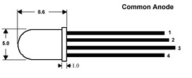
Pinouts:
Pin 1. Blue
Pin 2. Green
Pin 3. Common Anode
Pin 4. Red
- You should test your LED before connecting it to the Teensy board by briefly grounding the current-limiting resistors to ground, which should light the LED. Ask if you have a problem.
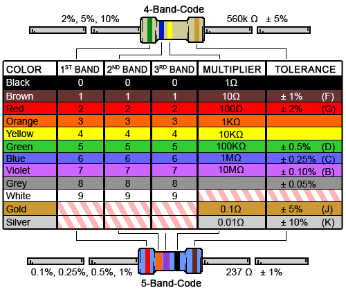
After testing, connect the LED Common Anode to the Teensy corner pin marked Vin (3.7 to 5.5 volts), the red segment to pin 20 via a 560Ω current-limiting resistor, the green segment to pin 21 via a 330Ω current-limiting resistor, and the blue LED to pin 22 via a 300Ω current-limiting resistor. It is okay to substitute the resistors for nearby values if the exact ones are not available, but err on the side of less current through the LED instead of more. Resistors are in the rightmost black cabinet on the back wall of the lab, next to the door of 003D.
- Next, Write a new version of your IntervalTimer sketch from Section A called tricolorTimer, and modify it to blink each color for one second in succession: Red, Green, Blue. You will need to keep track of three states. Your variable blinkCount could be used as a modulo-3 counter. The Arduino serial debug window can be used to check your variable .Note that since the LED is common-anode, OFF is a 1 and ON is a 0 on the respective port pins.
Demonstrate your tricolorTimer sketch to your TA.
Section D: Pulse-Width Modulation
- For Pulse Width Modulation we will use the analogWrite() function in Arduino (see references in Suggested Reading). Read that material to start.
- Construct a new version of your tricolorTimer sketch called PWMtimer which fires the timer every 10 milliseconds. Your code should change a variable for each LED in succession, so that RED fades up (255 to 0) and then down (0 to 255), followed by Green fading up and down, and then by Blue fading up and down, and the cycle repeats.
- Finally, see if you can incorporate your potentiometer and ADC code from lab one to change the fade rate. You may need to back up to your blink sketch in Lab 1 which uses the delay function to set the timing of your analogWrite() function calls. Call the new sketch ADCfade.
Question 6: Is the LED affected by the period of the PWM output, or by the duty cycle (on time), or both? Can you run it too fast or too slowly?
Demonstrate your PWMtimer and ADCfade sketches to your TA.
Deliverables
E-mail a single .zip file containing all required documents to your Catalyst Drop Box: https://catalyst.uw.edu/collectit/dropbox/papah/36517
For all files turned in, the comments at the top of the file should contain:
- Your full names and student numbers.
- The lab number and the part of the lab (e.g. "Lab 2, Section C" for your source).
- Answers to the SIX Lab Questions.
- Commented Sketches for Sections C and D (tricolorTimer, PWMtimer, and ADCfade).