Servos usually have a limited angle of rotation. Some modifications must be made to make them turn continuously.
Once the servos have been modified, they must be calibrated, please see this document.
Now attach the wheels to the servos using screws, and attached the servos to the chassis. In our instance we mounted them along the underside of the cardboard panel, and in the front.
Next we attached the back wheel. We used a couple of Lego pieces attached to the underside of the cardboard to offset the wheel. Through the lego pieces, we drove a pin for the wheel to rotate around. On both sides of the wheel, we filled the gap with washers to prevent the wheel from moving along the pin.
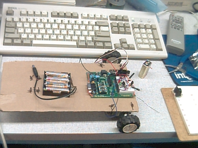
Attach the breadboard to the bottom of the chassis (our piece of cardboard). Towards the front of the robot, centered between the servo motors. The battery pack is then attached to the top of the robot towards the back.
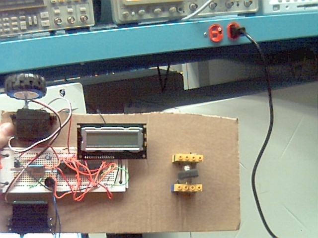
Build the circuitry using the 8051, the LCD, the speaker, and the pushbutton as shown
Build the circuits for the infrared object detection, whisker object collision, and remote control as shown.
Then attach the BOE to the front center of the chassis. You may then plug in the servos into the servo ports on the BOE. Left into port 15 and right into port 14.
At this point, your robot should be complete... at least the building phase.