The schematic is a JPEG file that is quite large (about 1 MB), clicking the link will open it in the current window, or you may right click it and choose "Save As".
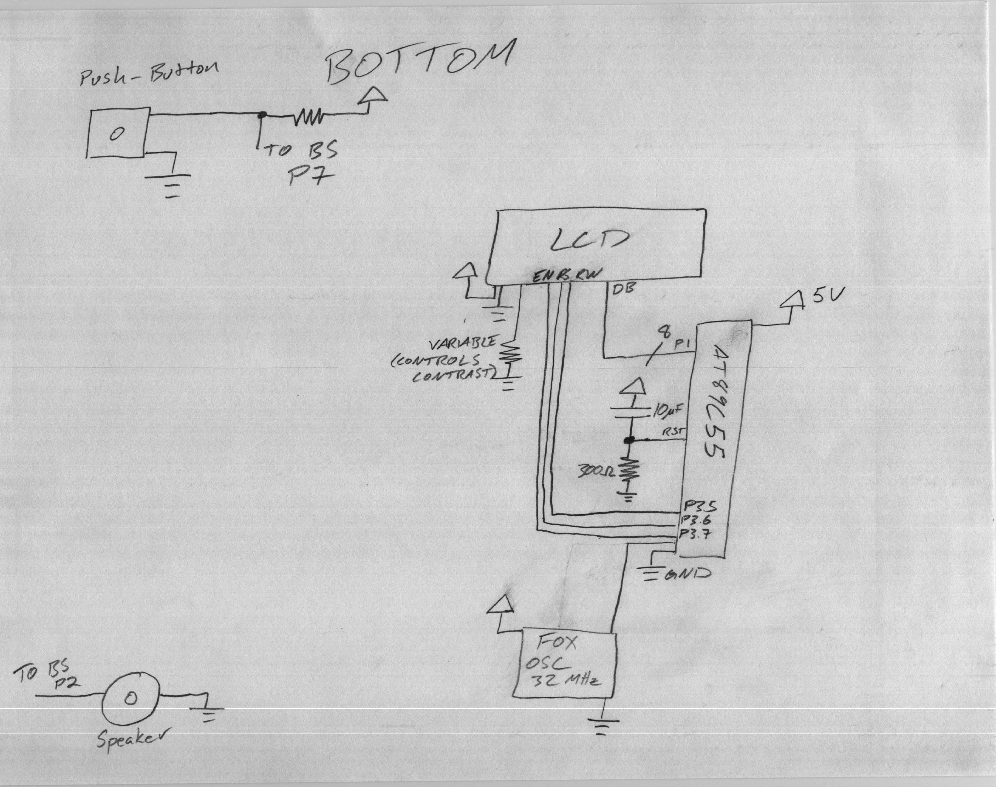
Schematic-Horizontal (better for viewing on computer screen)
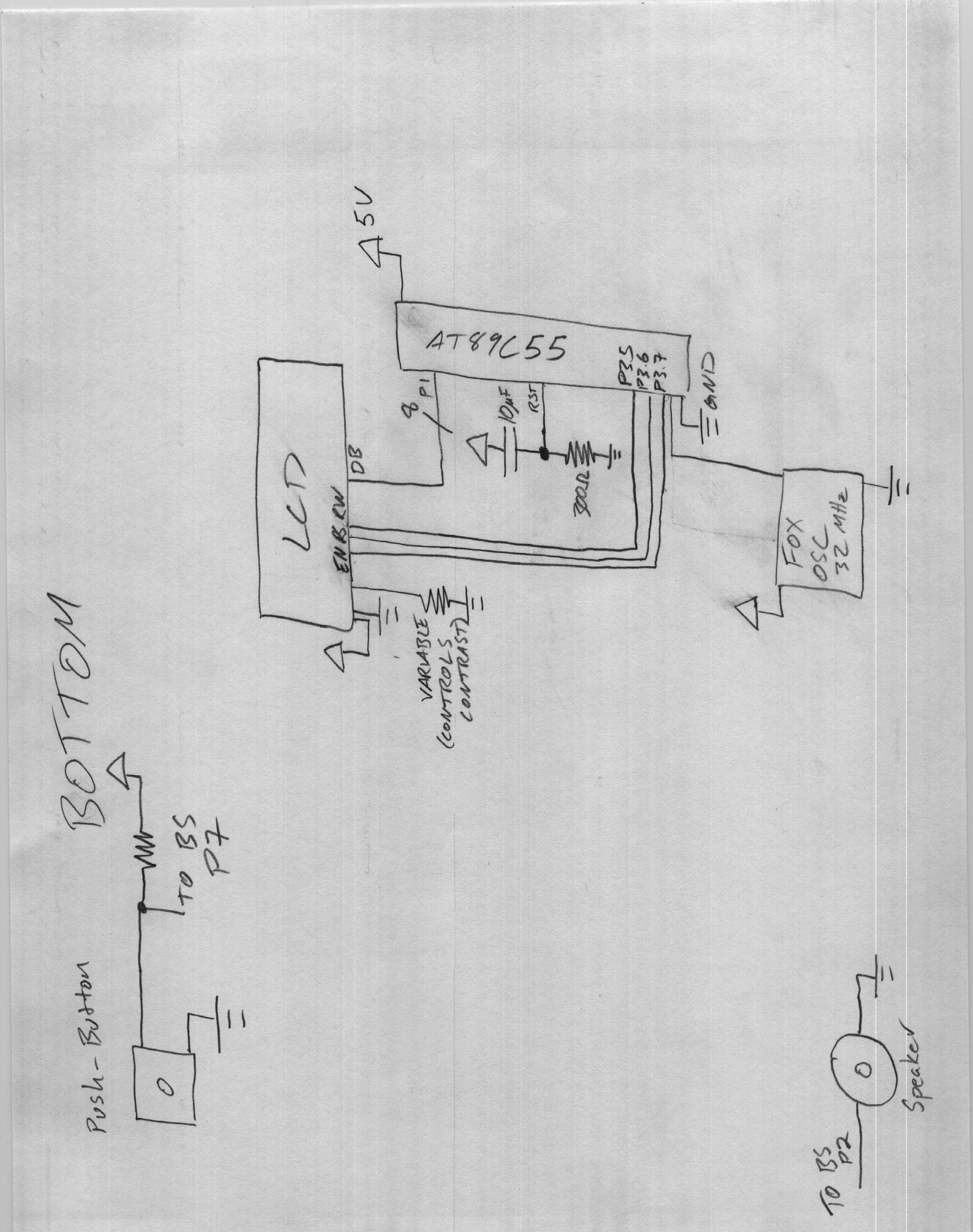
Schematic-Vertical (better for printing)
Connect the longer wire of the speaker to P2 on the BASIC Stamp. Connect the other to Ground.
Connect one of the Push Button Contacts to Ground, connect the other to a 300 Ohm resistor (NOTE, this is NOT labeled on the schematic) to Vdd (+5V). Make a connection between the push button and the resistor that goes to P7 on the BASIC Stamp.
The little divit marks pin 1. Connect the pin directly opposite pin 1 to Vdd. Connect pin 20 (the bottom, same side as divit) to ground. Connect the 2nd pin directly above this (3rd from bottom) to the oscillator. Connect the 9th pin down to a 10 micro-Farad capacitor that connects to Vdd, and this pin should also connect to a 300 Ohm resistor that connects to ground. (This stuff connected to pin 9 is the reset circuitry).
Connect port 1 to the Data ports on the LCD. Connect P3.7 to the EN on the LCD. Connect P3.6 to the RS on the LCD. Connect P3.5 to the R/W on the LCD. Connect the LCD to Vdd and to ground. Connect a variable resistor into the contrast pin to control the darkness of the screen.