An ABEL source file is basically an ASCII text file written according to the requirements of the ABEL-HDL language. A source file may contain any number of modules, each with a logic description. You can write a source file using any word processor or text editor that produces ASCII files, such as the simple editor provided in the ABEL design environment. You can click here to see what a template source file in ABEL looks like. Below, we describe how to create the source file from scratch by writing the ABEL source code for the calendar system. Following that we also give an example of the ABEL source code by providing the code for the full subtractor.
We will go to the Synario Project Navigator and start up a new project. This time, instead of declaring the source as a schematic, we'll declare it as "ABEL-HDL Module" instead of "Schematic" or "Verilog Test Fixture" as shown below:
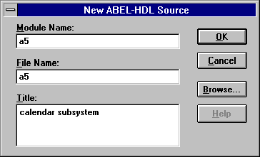
Clicking on ok, we'll be prompted for the module name, the file name, and the title of our file(see figure below). The module name supplied here would be the name of your ABEL-HDL module. The title name gives the title for the module hence you should choose a title that will be unique and descriptive and that helps you remember the function of the module. Frequently, the module and the file name are the same. However, the file name will be appended with the .abl extension. For this project, we are going to be specifying a calender subsystem that takes as input a month and a leap-year flag and returns the number of days in the month.

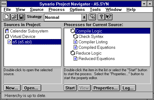
Now when we click "OK" two things will happen. An ABEL file is included as a new source to our project (notice the "A" in the icon for the source file in the snapshot below) with a .abl extension and a text editor window is opened containing a template file for our module.
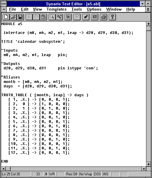
The Text Editor allows us to enter a textual specification of the logic we want in our module. In this case, we'll specify the month as a four-bit binary number and the leap year flag specifying whether the year is a leap year. The output is the number of days for that month.
First, we must enter a specification for the inputs and outputs.
MODULE calendar

 interface (m8, m4, m2, m1, leap -> d28, d29, d30, d31);


TITLE 'calendar subsystem';


"Inputs


  m8, m4, m2, m1, leap     pin;


"Outputs

  d28, d29, d30, d31       pin istype 'com';


"Aliases

  month = [m8, m4, m2, m1];

  days  = [d28, d29, d30, d31];
The portion of the file shown above specifies the interface of the module (inputs -> outputs)and the pins. This is done with the keyword interface. The module statement is a required element of the source file. The module statement defines the beginning of a module and must be paired with an END statement that defines the module's end.The module name given determines the name of any output files created during processing by the ABEL software. The title is inserted in the source file to give a title to the module. The title statement and the description are optional. Note that in ABEL, any line that starts with a double-quote (") is a comment line (that is, the rest of the line after the quote is ignored- you do not need to close the quote). Therefore, the words "Inputs" and "Outputs" are not of any significance to ABEL. We specify the type of the outputs by using the istype keyword. In this case, we have combinational logic so our outputs are of type 'com'. We also include some aliases that group a collection of signals under one name so that we can refer to the entire group as a unit.
There are many different ways to enter a specification for the logic in many different ways. We'll go through a few in this tutorial. These are basically

We first start with the Truth Table method. Truth tables are an alternative method for describing both combinatorial and sequential circuits. A truth table consists of a truth table header and truth table entries. The truth table header defines the inputs and outputs of the function. The header is followed by a sequence of truth table entries that define the required output values for each possible set of input values. Hence the truth table is specified by listing all the input combinations we care about and their corresponding outputs. Notice how the number of bits must match precisely with the specification given at the beginning of the truth table ( 5 inputs--month (4) and leap (1) -> 4 outputs--days (4).) The month inputs alias allowed us to use decimal numbers for the month rather than binary values (this is why the order of the month inputs in the alias statement was important--high order bit to low order bit). Note also the use of .X. to specify a don't care input. This tells the ABEL compilers that for any value of that particular input the output values should be the same. Finally, note that we did not list all the possible input combinations. The presence of the .X.'s gave ABEL a hint that it should use the input combinations not listed as don't care conditions. However, in general, ABEL does not do this. To ensure that ABEL takes advantage of this sort of don't care information you can declare an output to be istype 'dc, com'.
We are now ready to compile our specification and see what the result is. Synario keeps track of all the steps required in compilation. Select the ABEL source in the "Sources" sub-window and then double-click on "Reduced Equations" in the "Process" sub-window of the navigator.

The resulting file is a5.eq1 and it contains, among other things, the following equations for our four outputs:
 EQUATIONS:

    d28 = (!m8 & !m4 & m2 & !m1 & !leap);
d29 = (!m8 & !m4 & m2 & !m1 & leap);
    d30 = (!m8 & m4 & !m1
          # m8 & !m4 & m1);


    d31 = (m8 & !m2 & !m1

          # m8 & !m4 & !m1

          # !m8 & m1);
In the ABEL source, instead of using truth-table we can write equations for each of the outputs directly. ABEL will still minimize them for us. We could replace the truth table block with:
EQUATIONS
d28 = ( !m8 & !m4 & m2 & !m1 & !leap);
d29 = ( !m8 & !m4 & m2 & !m1 & leap);
d30 = ( !m8 & m4 & !m2 & !m1 # !m8 & m4 & m2 & !m1
# m8 & !m4 & !m2 & m1 # m8 & !m4 & m2 & m1);
d31 = ( !m8 & !m4 & !m2 & m1 # !m8 & !m4 & m2 & m1
# !m8 & m4 & !m2 & m1 # !m8 & m4 & m2 & m1
# m8 & !m4 & !m2 & !m1 # m8 & !m4 & m2 & !m1
# m8 & m4 & !m2 & !m1);
Equations specify logic functions with an extended form of Boolean algebra. An ending semicolon is required for each equation. Note in the above equations the symbols used for not, and and or. Not is represented by !, and by & and or by #. The equations statement defines the beginning of a group of equations associated with a device. The equations following the equation statement are any valid ABEL-HDL equations as described in the ABEL-HDL language structure. The resulting minimized equations are same as before. ABEL performs the two level minimization for us.
Yet another way of specifying logic functions is to use programming language constructs such as WHEN-THEN-ELSE. If we want to use this construct instead of the Boolean expressions stated earlier we would replace the EQUATIONS section by :
EQUATIONS
WHEN (month == 2) THEN { "if its February
WHEN (leap == 1) THEN "and its a leap year
days = [0,1,0,0]; "then its 29 days
ELSE
days = [1,0,0,0]; "otherwise its 28 days
}
ELSE {
WHEN ( (month == 4) # (month == 6) # (month == 9) # (month == 11) ) THEN
days = [0,0,1,0]; "cases where its 30 days
ELSE days = [0,0,0,1]; "31 days for others regardless of month }
Now, if we compile the equations as we did for the truth table method we'll see that minimized equations are not exactly same as before. The reason is that, in the truth table method we used don't cares .X. whereas here we are asking for the output to be [0,0,0,1] for all cases besides 2, 4, 6, 9, 11. Hence, the compiled equations look like:
Equations:
d28 = ( !leap & !m1 & m2 & !m4 & !m8);
d29 = ( leap & !m1 & m2 & !m4 & !m8);
d30 = ( !m1 & m4 & !m8 # m1 & !m4 & m8);
d31 = ( !m2 & !m4 & !m8 # m4 & m8 # m1 & !m8 # !m1 & m8);
In the above compiled equations, note that although the equations for d28, d29, and d30 are the same, the equation for d31 is quite different. In fact it includes 0,13,14, and 15. In order to get the same equations as before we need to specify that we don't care what the values are for 0, 13, 14 and 15. We can do that as follows:
EQUATIONS
WHEN (month == 2) THEN { "if its February
WHEN (leap == 1) THEN "and its a leap year
days = [0,1,0,0]; "then its 29 days
ELSE
days = [1,0,0,0]; "otherwise its 28 days
}
ELSE {
WHEN ( (month == 4) # (month == 6) # (month == 9) # (month == 11) ) THEN
days = [0,0,1,0]; "cases where its 30 days
ELSE WHEN ( (month == 1) # (month == 3) # (month == 5) # (month == 7) # (month == 8) # (month == 10) # (month == 12) ) THEN
days = [0,0,0,1]; "cases where its 31 days
ELSE days = [.X.,.X.,.X.,.X.]; "don't care about others
}
The compiled equations now obtained should be the same as we are providing the same information.
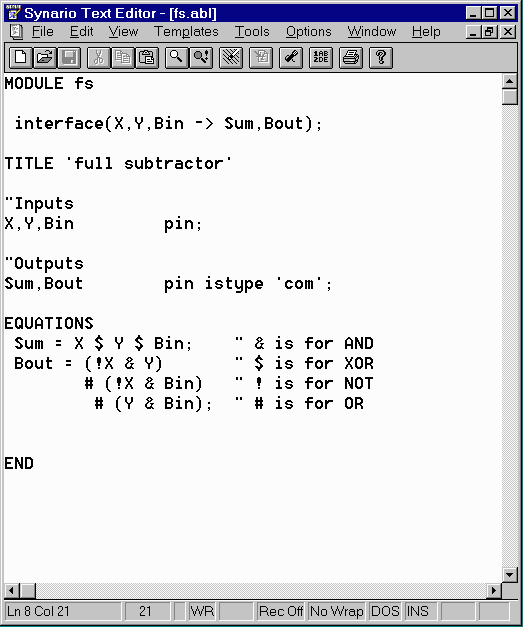
Concept of the ABEL-HDL language would become more clear once we redo the homework assignment #3 using ABEL instead of the schematic. For this we will open a new project and create a new ABEL source and enter the following:

On compiling the ABEL source file, we obtain the fs.eq1 file which contains the following equations:
Equations:
Sum = (X & !Y & !Bin
# !X & Y & !Bin
# !X & !Y & Bin
# X & Y & Bin);
Bout = (!X & Y
# Y & Bin
# !X & Bin);
After compiling, we can now use the ABEL-HDL module as we would have used any module specified with the schematics editor. We can create a new "Verilog Test Fixture" source and simulate the design. The process is same as in the previous tutorial and will not be repeated here. We could also use the ABEL module as a sub-module in larger design. Click here to see how that is done.