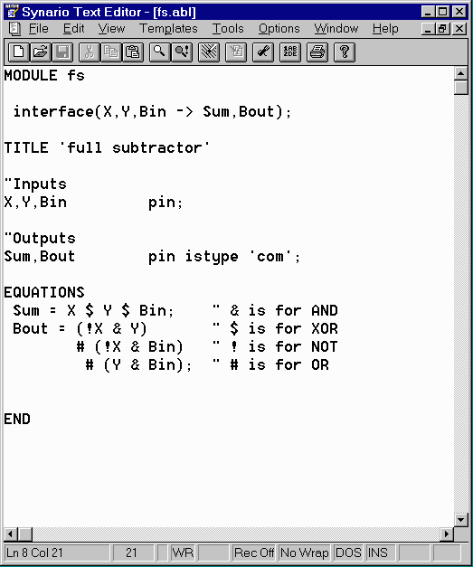
We can create block symbols using ABEL module just as we did for the schematic. Block symbols are important in large designs when you want to use an ABEL module as a sub-module in larger design. We can create the four-bit subtractor(from the past homework assignment) by using block symbol that includes the ABEL file for the full-subtractor for the specification of it's functionality. The ABEL file for the full subtractor is shown below:

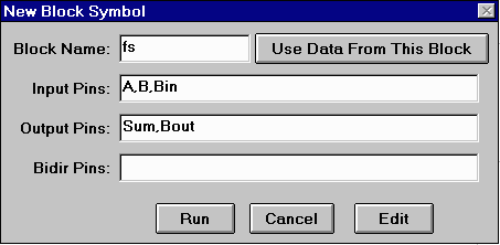
In order to use this ABEL file in larger design we would first have to create a block symbol for this ABEL file. To do this, we first start another project with a schematic source. The schematic editor will start up with an empty sheet. We will enter the top-level design of the four bit subtractor and then link it to the full-subtractor ABEL code as a sub-module. We begin by selecting "New Block Symbol.." from the "Add" menu and the following to specify the full-subtractor sub-module.

Clicking on the "Run" button creates a block symbol for the full-subtractor and can be used as a sub-module in larger design. Note that we have not yet attached any functionality to this module. We can do that by using this module in the scheamtic for the four-bit subtractor. We construct a schematic diagram that looks like the following:

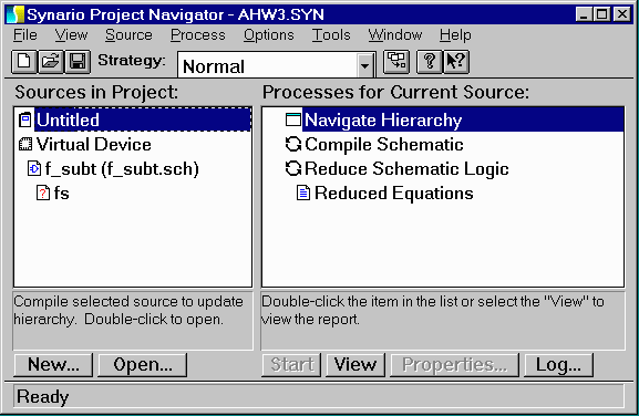
When you save this scheamtic, you'll notice that the project navigator window now shows that a sub-module of unkown type is being used in this project. It shows this by adding a question mark in front of that sub-module like so:

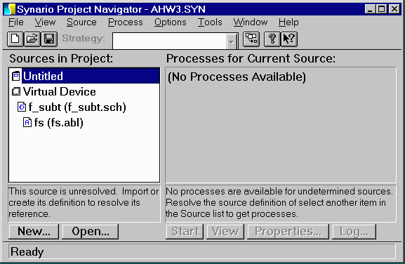
It is now time to attach a source file to this sub-module definition. You can do this by selecting the sub-module in question (indicated by a question mark) in the "Sources" sub-window of the project navigator and then selecting "Import.." from the source menu. You can then select the ABEL source file for the full-subtractor that we had previously defined. After doing this, the question mark should disappear and the project navigator would look like this:

If the question mark does not disappear that means that synario cannot associate the sub-module with the specified ABEL file and this mainly occurs if your block name (while creating the block symbol) is different from your ABEL module name. We could now create a new "Verilog Test Fixture" source and simulate the design. This is the same process as in the previous tutorial and will not be repeated here.