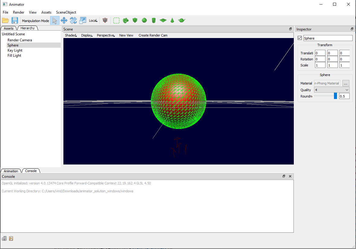
The Hierarchy tab in the left pane represents all the objects in the current Scene. A child object inherits the transformations applied to the parent object like in a scene graph. Parent-Child relationships can changed by simply dragging the objects around in the pane. You may also find creating Empty objects as parents to be useful in building your model. Double click an object to change its name.
The Assets tab in the left pane represents things like Textures, Shaders, Materials, and Meshes used by the Scene. Materials use Shaders, and shaders use .vert and .frag files. You can either edit them in the right-side Inspector, or choose to create a new asset. Together, the Assets and Scene Graph form a "Scene", and can be saved out or loaded from disk.
Selecting an asset or an object will display their properties on the right side in the Inspector. Here you can change their properties, assign different textures, materials, etc. For scene objects, you can also hide them from the hierarchy by unchecking the box by their name.
Modeler uses a component based system for scene objects. Every object has a "Transform" component that represents their Translation, Rotation, and Scale in 3d space. Most rendered objects will have a "Geometry" that defines the shape of the object, and a "Mesh Renderer" that uses a "Material" asset to define how to render that shape. Lights will have an additional "Light" component that defines the light properties.
Console at the bottom is mostly for debugging purposes, at any time in your code, you can call Debug::Log.WriteLine to print to this console. If you hide the Inspector or any of the other panels in the program, right-click on the tool-bar to show them again.
Scene in the middle is a rendering of your Scene Graph. You can change how its rendered as points, wireframe, or fully shaded via the menu bar along the top of the scene view. If you are having trouble with the orientation of the Perspective view, try switching to an Orthographic view.

Camera Controls:
Scene Controls:
Loading a Mesh (.obj/.ply files):
The high-level idea is to import the mesh as an asset, and create a mesh whose TriangleMesh::Mesh property is the mesh asset you just imported.
Creating a new shader:
The Modeler codebase is quite substantive (not so much a skeleton this time around). It's a good idea to get an understanding of what's going on.
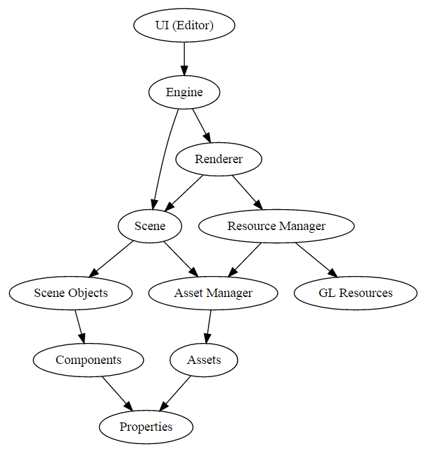
Modeler has two major components: the Engine and the UI. For the requirements, you will most likely only be concerned with the Engine unless you attempt a bell or whistle that goes above and beyond what is currently supported. Modeler loads one Scene at a time. Each Scene has an Asset Manager that handles loading all the Assets belonging to the Scene. It also owns all the Scene Objects in the scene, which are stored in a map using unique identifiers.
A Scene Object contains a mixture of Components that define some behaviour. For instance, a Transform Component which defines the Scene Objects transformations + a Point Light Component which defines light properties, makes a Point Light. Components are built from Properties that are able to communicate responsively with the UI, and can be serialized into the file format. A Renderer takes a Scene and does a depth-first traversal of the Scene Objects that comprise the Scene Graph and renders each component that is renderable. It has its own Resource Manager that handles caching GPU versions of assets.
For a more in-depth explanation on the codebase, please visit this document.
In OpenGL, all scenes are made of primitives like points, lines, and triangles. Most 3d objects are built from a mesh of triangles. In this project, you will implement a surface of revolution by creating a triangle mesh. For each mesh, you define a list of vertices (the points that make up the primitive) with normals and texture coordinates, and an array indices specifying triangles. This is then later used by the OpenGL Renderer through the method glDrawElements. See opengl/glmesh.cpp.
Surface normals are perpendicular to the plane that's tangent to a surface at a given vertex. Surface normals are used for lighting calculations, because they help determine how light reflects off of a surface.
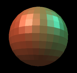
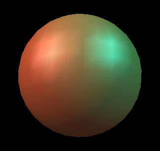
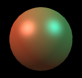
In OpenGL, we often want to approximate smooth shapes like spheres and cylinders using only triangles. One way to make the lighting look smooth is to use the normals from the shape we're trying to approximate, rather than just making them perpendicular to the polygons we draw. This means we calculate the normals for each vertex (per-vertex normals), rather than each face (per-face) normals. Normals are supplied to OpenGL in a giant array in the same order the vertex positions array is built. Shaders allow us to get even smoother lighting, calculating the normals at each pixel. You can compare these methods below:
Texture mapping allows you to "wrap" images around your model by mapping points on an image (called a texture) to vertices on your model. For each vertex, you indicate the coordinate that vertex should apply to as a 2D pair (U, V) or (S, T) where U or S is the X-coordinate and V or T is the Y-coordinate of the point on the texture that should line up with the vertex. UVs are passed as a giant array in the same manner normals and vertex positions are:
When you want to use a texture, you'll need to do the following:
Import a texture into your scene
Create a Shader Program that utilizes shaders that sample from textures
Create a Material that uses that Shader Program, and set the textures
To verify the correctness of your implementation, follow this steps:
Go to [SceneObject->Create 3D Object->Surface of Revolution], then you will see a mesh called "Surface of Revolution 1" in the scene hierarchical panel.
Select the object your just created, on the right inspector panel change the curve property as "assets/curve/sample_curve_1.apts" or "assets/curve/sample_curve_2.apts". Observe if the output is the same as the solution.
(Optional) You can also design your curve and the rebuild a mesh accordingly. In the solution program (not in your program), open the curve editor [File->Open Curve Editor], follow the instructions to create your curve, and then save the curve by clicking "Save Dense Samples". Finally, go back to step 1 to select the curve file you just saved and create the mesh.
For the artifact, you will create a Hierarchical Model. Create a hierarchy of nodes, a combination of Empty nodes and Shape nodes. In Animator, you will end up animating your Model(or you can create a new one) by manipulating the set of transforms and other properties on all these nodes over time. Hide any properties you do not want exposed with the Inspector's "Edit Properties" on each node.
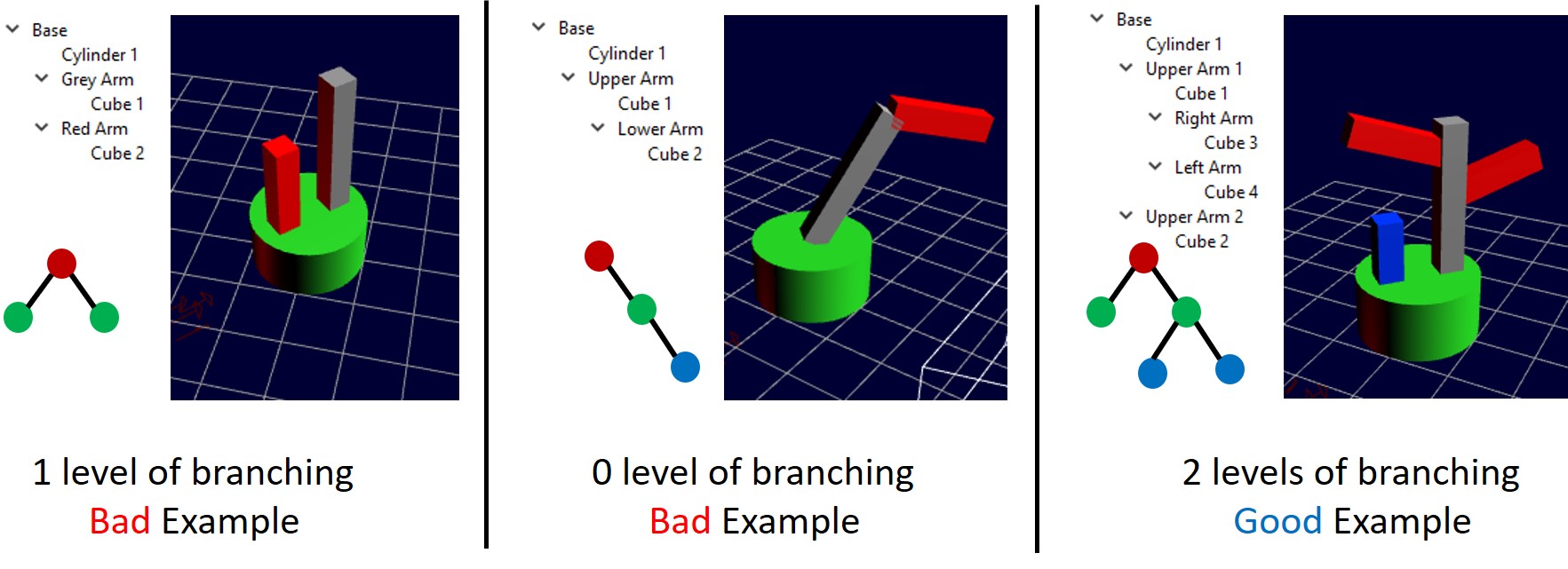
While it does not have to be a masterpiece, we do require that it has at least two levels of branching. What this means is that if you have a torso, and attach two arms to it, this is one level of branching. The torso splits into each arm. If each arm then has three fingers, that is two levels of branching, since the arm splits into fingers. Note that if you only have one finger, then that does not add additional branching! Below we show two bad (left, middle) and one good (right) examples to help you further understand the "at least two levels of branching" constraint.
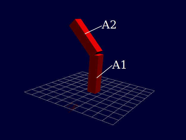
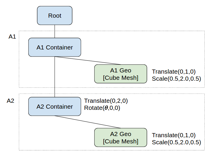
Writing down a tree diagram that illustrates the model hierarchy and describes the transforms that each node has can be very helpful in designing a model. Here is a very barebones example of the tree diagram of a simplest robot arm, consisting of two long boxes with a single joint in the center. Note that this example only has one level braching, which means it does not have the required amount of branching.
Note you do not have to submit a diagram of your model. This is just a recommendation, not a requirement.
When demoing your model, or when keyframing it for your animation, you don't want to be clicking down into different hierarchy nodes all the time in order to reach the right properties. You could instead have a master set of sliders that you can easily manipulate.
For example, in the simple hierarchy above, clicking down into the "A2 Container" node each time you want to change the joint angle is somewhat tedious (and will only get harder with more complex hierarchies). For this requirement, you will add some UI elements to control the variables in your hierarchical model transformations.
The easiest way to do this is to create an empty node, that is your root node, at the top level of your hierarchy, which will serve as a container for your Hierarchy UI. Then, you can implement a UI component and attach it to the root node to help you control the model, without tediously going down the tree to apply the transforms.
We've implemented most of Model UI codes for you. As shown in the figure below, you just have to follow the three steps:
CustomProp::OnAngleChanged(double angle) in Engine\src\scene\components\cusomprop.cpp. We provide code snippets in the function to guide you how to parse the scene, find components, and change values. It's also very easy to add more control properties in the same class. Taking a closer look at the commented codes in the class CustomProp, you will know how it works.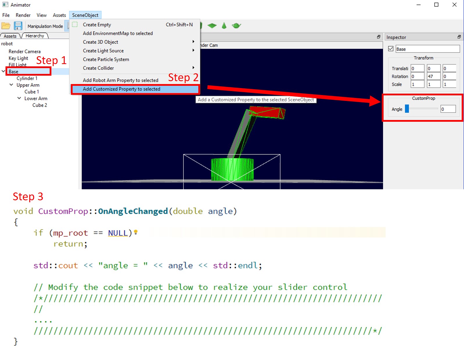
A shader is a program that controls the behavior of a piece of the graphics pipeline on your graphics card.
Vertex shaders are run once for each vertex in your model. They transform it into device space (by applying the modelview and projection matrices), and determine what each vertex's properties are.
Fragment (or pixel) shaders are run once for every pixel to determine its color.
Geometry shaders can turn a single point into multiple points. They are useful for advanced modeling, e.g., refining a coarse triangle mesh into a smooth surface with many triangles. They can also be used to visualize vertex normals. But they are not part of this requirement.
Shaders determine how the scene lighting affects the coloring of 3D surfaces. There are two basic kinds of lights:
Point Light - a light that is emitted from a point in world space. The intensity of the light is attenuated (reduced) based on how far it travels from this point. In the physical world, the intensity of a point light decreases with the square of the distance. We can model this with quadratic distance attenuation: dividing the intensity by some function a*r^2+b*r+c, where r is the distance from the light source and a, b, and c are chosen arbitrarily.
Directional Light - a light that always hits a surface from a certain direction, no matter where it is. It has no attenuation.
A shading model determines how the final color of a surface is calculated from a scene's light sources and the object's material. We have provided a shader that uses the Blinn-Phong shading model for scenes with directional lights. See lecture notes for details on the Blinn-Phong shading model.
Note after building your program via QT Creator, you will have two copies of shader files, one is in the project folder and the other is in the binary folder. We basically copy the shaders from the project folder to the binary folder when the program is opened. So when editing the shader file, remember to edit the shader files in the project folder, not the binary folder, since they will be overwritten when the program is lanuched.
To verify your implementation, you need to put a point light source in your scene. We provide a example scene including a point light for you, which is located at assets/scene/point_light_scene.pyml. You can just open the scene in both your and the solution program to see if the rendering results are the same.
These are additional shader ideas that you can create. You are required to create another shader(s) worth at least 3 whistles (or 1.5 bells). Additional bells or whistles are extra credit.
You can use the sample solution Modeler to develop some of these shaders, but others require texture maps to be provided. We have provided shader_textured.frag and shader_textured.vert as reference for you on how to include texture data into your image.
See here or Program Usage: Creating a new shader for instructions on how to use your shaders in your model.
For your reference, in the solution, we provide a very cute shader, called cartoon shader (it is worth 1 bell if you implement this!). You just open the soluton, select a mesh, and change the material as "Toon Material". Check it out to see what it looks like.
|
Alpha Test Shader
Some geometry has complex silhouettes but flat, planar surfaces. Rather than creating numerous triangles, we can use an alpha threshold or color key to discard certain pixels on a texture. This technique is especially useful for foliage. You should be able to see other objects through the transparent areas (but it is ok if its own backface is not visible). For an extra whistle, make it cast alpha-tested shadows too. |
|
|
Reflection Shader
Create a shader that simulates a reflection effect by determining a reflected ray direction and looking up that ray in an environment map. To implement this, note that any geometry node with an |
|
|
Refraction Shader
Create a shader that simulates a refraction effect by determining a refracted ray direction and looking up that ray in an environment map. See the shadow mapping section above for more details on obtaining the environment map. Note that there are two reasons why this isn't an accurate refraction shader. First, a true refracted ray should get refracted once upon entering the object and once upon leaving it, while here we can only refract the ray once. Second, the environment map is only an approximation (a so-called "distant scene approximation") of the incident light on the object. For example, a ray pointing in direction v at the top of the object will look up the same environment map value as a ray pointing in direction v at the bottom of the object, but the true incident light along those rays will only be equal if the surface in direction v is infinitely far away from the object center. |
|
|
Spot Light Shader
Create a shader that supports a spot light source, and add a third light source to your Modeler. We should be able to adjust the spot light parameters via the UI. |
|
|
Cartoon Shader
Create a shader that produces a cartoon effect by drawing a limited set of colors and a simple darkening of sillouettes for curved objects based on normal and viewing direction at a pixel. This per-pixel silhouette-darkening approach will work well in some cases around curved surfaces, but not all. Additional credit will be given based on how well the silhouettes are done, and how well the cartoon effect looks. |
|
|
Schlick Shader
Create a shader, and sliders to control it, thatnuses the Schlick approximation to approximate the contribution of the Fresnel factor to the specular reflection of light. |
|
|
Vertex Shader
Vertex shaders, instead of transformation matrices, can be used to morph and deform geometry in complex ways, and it can be really efficient since the calculations are run on the GPU. See here, here, and here for examples of interesting geometry deformations done with vertex shaders. And see here for an even more impressive example: the swimming animation is done entirely by manipulating vertex positions in the vertex shader. Add at least one slider that deforms geometry in a useful way by changing vertex positions (and normals, if relevant) within a vertex shader. |
|
|
Tessellated Procedural Shader
Make a shader that produces an interesting, repeating pattern, such as a brick pattern, without using a texture. |
|
|
Normal Mapping Shader
This shader uses a texture to perturb the surface normals of a surface to create the illusion of tiny bumps, without introducing additional geometry. Along with the normals, you'll also want your vertex shader to take in tangent and binormal vectors. |
|
|
Diffraction Shader
Create a shader that produces a diffraction effect when you move around the object. |
|
| x2 |
Anisotropic Shader
Create a shader that produces anisotropic specular highlighting, creating a shiny metal appearance. Additionally, add sliders to control the magnitude in 2 perpendicular directions. |
| x3 |
Cloud / Noise Shader
Create a shader that uses noise functions (like Perlin noise) to generate clouds. You may not use textures for this shader. Credit depends on the realism of the clouds. |
Shader files are loaded, compiled, and linked by ShaderProgram objects. If you want to add a shader:
Go to Assets->Create->Shader Program to create a Shader Program.
Find the new shader in the Assets pane and set the Vertex/Fragment shaders to point your shader files.
Similarly create a new material and set it to use the Shader Program you created.
Tip: If you have an error in your shader code, you do not have to restart modeler. Instead, fix your shader, then just set Shader Program to point to the same shader file again. You can also reload your assets after any changes by clicking Assets->Reload Assets.