This is a common idea used in a lot of the computer rendered graphics you see around. Height fields are the basis of all the wonderful hills and mountains you see a lot of people putting in their images. Bryce 3D is a program famous for it's height fields. In fact, that Digital Blasphemy website that a lot of people in the class have been browsing through and looking at (drooling over? or is that just the TA's?) recently uses a ton of height fields, almost in every image. Every mountain, every hill, every ski-slope, every cliff... All height fields. [1]
So, how does one do it? Well, Start by reading a flat picture, color or greyscale into a program. We'll be going through this image a few pixels [2]at a time, building triangles as we go.
The algorithm is this: Take a little square of four pixels from
this image and imagine them sitting all by themselves. Each one has an
X and Y coordinate, taken straight off the image. The lower left pixel
is (0,0) and the upper right is (1,1). Our goal is to generate two triangles
in 3D space from these four pixels. In the diagram below, each of our four
pixels is marked as an 'x' and the two triangles we'll make are
drawn in.
         x---------x (1,1)
         |       / |
         |     /   |
         |   /     |
         | /       |
 (0,0)   x---------x
Each pixel has an X and Y already. So, we can already write down the vertices for two 2D triangles:
Triangle 1: (0,0) (0,1) (1,1)
Triangle 2: (0,0) (1,1) (1,0)
All we need is turn these 2D coordinates into 3D coordinates somehow, and for that we just need a Z value for each pixel. So, we look at the image again and find what information we haven't used yet -- the intensity of each pixel. We take each of our four pixels and calculate how bright it is [3]. We use this brightness, scaled into some appropriate range, as the Z value.
You look at a square of four pixels and calculate the intensity of each pixel. Then, you use these four intensity values as the four Z coordinates. Voilla, we have two triangles in 3D space generated from four pixels. Move over one square in the image, and make two more triangles. Move over again, and repeat. The two figures below show this process better. [Taken from the POVRay documentation.]
A region of four pixels mapped into different heights. The shade of grey of each pixel (the square-shaped regions at the bottom) represents the brightness of that pixel. The two triangles generated from these four pixels are shown, where the height of a vertex above the image is calculated from the pixel brightness.
A larger region, showing how all the triangles of an entire image
relate to one another. This whole image has been scaled to be in the range
of 0 to 1 along each axis.
When you're done, you have a whole mesh of triangles generated from the image. What this mesh looks like in 3D depends on what the basic image looked like. To make the image look really pro, you can assign each vertex a color and let OpenGL do smooth shading between them. Using the colors from each pixel in the input image as the colors for the corresponding vertices is probably the easiest, though there are other ideas you could also tackle.
So, one final question, what part of the projects does this cover?
The answer is extra credit. I could see ways to work this into either project
2 or 3. In project 2, being able to draw height fields at all is above
and beyond the requirements, by a goodly amount. Doing a height field would
not supplant making a character, but a height field could augment your
scene. Maybe a ground for your character to walk on? Or maybe use a height
field to model spikey "hair" on top of his/her/its head? [4]
The possibilities are up to the imagination. In project 3 (raytracer),
this is a wonderful add-on that would let you render some REALLY cool scenes.
As an extra, add in your own smooth shading (see Gouraud Shading in Foley
et al.) for an extra bunch of coolness. (This is not easy at all.) In project
4, well, the possibilities in project 4 are a little more limited, but
still you might be able to come up with something.
Final warning: I should also say that this is slow and CPU intensive.
If you want to work large meshes of triangles into your project 2 model,
I'd seriously look at the last half of chapter 2 in the Woo et. al. OpenGL
Programming Guide (the maroon book) where it talks about arrays of vertices.
You might have to play around to see just how complex a triangle mesh you
can get before the system chokes. We have good graphics engines, so they
should be able to handle hundreds of polys at a time without even a burp.
Still, keep in mind that there is an upper limit.
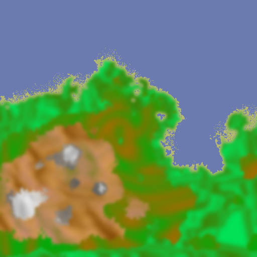
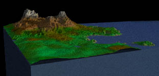
Below is a sample of a progression from flat images to a 3D landscape. The first image is a greyscale image that gets used as a height field to find the elevation of each vertex. The second image is used to find the color of each vertex. Splitting the images up this way allows for better color schemes, such as allowing bright colors in low elevations, or random speckles and texturing. In truth, this second "color" image is not part of the height field algorithm at all, but is an example of a texture map. I cheated by making the texture map and the height field the same size, so it is possible to just assign colors to vertices without any fancy averaging or scaling functions to make the image "fit" the surface.
The third and final image is a sample output of the final heightfield
and texture map. The output image was generated with a raytracer rather
than using OpenGL function calls in a library, though the results would
be similar.
[2] - The word "pixel" is almost a misnomer here. Pixel means "picture element" and is normally used to mean a dot on the screen. When we're talking about the bytes of an image in memory, we can call them pixels, but only barely. Texel, for texture element, might be a better name, but you're also welcome to make up something better. ;)
[3] - A greyscale image (all greys) makes this easy; you just use the grey value. For a color image, you would need to convert the RGB colors into an intensity using the standard formula: I = 0.299R + 0.587G + 0.114B. Another common alternative is to use a palletized image (like a GIF file) and ignore the colors completely, using the palette index as the Z coordinate.
[4] - I've seen a height field used to model the jagged points at the end of a broken matchstick before.