Update
2 ( 5.20.04 )
Nathaniel
Brown and Chris Mordue
Issues Resolved and
Pending
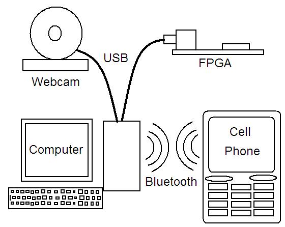
The major issue from update 1 was figuring out the bit-level logic for communicating with the USB webcam. We reached a dead end trying to figure out the webcam’s protocol so that we could connect it directly to the FPGA board. Thus we have resorted to our backup plan and our connecting the webcam to a computer and then sending the captured image over USB from the computer to the FPGA for resizing. Since we are already using the computer to connect to the webcam, we are going to send the resized image back to the computer and use a Bluetooth dongle to communicate with the phone instead of the personal server.
The other issue was figuring out the USB controller on the FPGA. We have partially figured this out and are able to send data to the FPGA and have it displayed on the boards 7-segement displays, and then read back these values to the computer. Expanding this so that we can send large amounts of data back and forth, such as images, is not fully understood. On the FPGA side there is a 16-bit data-in and a 16-bit data-out which seem to be asynchronous without data ready or taking data bits. We also need to figure out how to store data in the SRAM on the FPGA board, so that we can load an image to be resized.
Components and Their
Use
We now have all the components we need. We have a Logitech Quickcam (USB webcam) connected to our workstation computer. There is a SDK package (C++ libraries) from Logitech that will enable us to put the image frames in a memory buffer to be sent to the FPGA. After being sent via USB to the FPGA, the image is resized and sent back to the computer over the same cable. The FPGA is a Xilinx, Vertex 300 on a XESS XSV 300 development board, complete with SDRAM chips to buffer the webcam frames. The USB controller for the FPGA is a VHDL module from Trenz Electronic. We’ve had to add an external 48 MHz clock to the FPGA board for the USB controller.
The computer will then read and send the resized image data over Bluetooth via a Bluetooth dongle by 3COM. The Nokia 6600 cell phone will receive the data and display the image to the user. The cell phone is being programmed by Nokia’s SDK they provide.
Construction and
Debugging
The USB controller has been synthesized and successfully loaded on the FPGA. Transfer of 16-bit data packets from the computer to the FPGA and back again has been demonstrated using the USB controller. The next step is to scale this functionality up to larger amounts of data.
A C++ version of the code we wish to put on the FPGA has been implemented and tested. This code is devoid of divisions and multiplications to allow for easy conversion to Verilog. We are in the process of connecting the webcam to this C++ version. The next step is to write a small program to read the memory buffer location of the image and send that via USB to the FPGA. Concurrently, work will be done on the cell phone user interface and Bluetooth communication.
Design Schematic