Design Review of Group A’s
Preliminary Design Package
Brent Mikasa
Daniel Dunham
Curtis Mitchell
Overall, Group A’s planned and designed their project very
well. We did not find any flaws in
Stage I, but we did have some concerns in the other two stages. These concerns are listed below.
Stage II
There were two main issues that we saw regarding stage two: the use of polling for getting the digital signals from the lasers, and the code size of the controller module.
Using polling, especially when doing time-critical tasks such as music generation, is questionable. Depending on the structure of the code, if you constantly take the worse case path, the additional time needed for servicing the worse case code compounds, resulting in errors that may crash the system. Interrupts allow you to instantly jump to a portion of code at a given time or interval, making interrupts ideal for sampling of data. They take priority over normal code, so you do not need to worry that a long routine would keep the interrupt from being serviced.
Another related issue was the code size of the controller. The code size is limited by the sampling rate. For example, if 20,000 samples per second were performed, assuming a 32 MHz clock, it would require the sampling code to be run in under 133 cycles. If higher quality music is desired (48k samples per second was mentioned in the design package), the sampling code would only have 55 cycles to complete. Since there are twelve laser inputs, along with two pedals, this means it would take at least 14 cycles to examine all the inputs. Most likely it would take even longer because the Keil compiler does not produce optimum assembly code. This is shown in Figure 1, where a simple bit shift and assignment statement is expanded into the corresponding assembly code. In addition, the timestamps will need to be examined to determine the length of time one’s finger is held in the path of the laser. If the computations are very complex, it would be very easy to exceed the maximum of 55 cycles. We don’t foresee this being too difficult of a problem to overcome because it can be solved by careful coding, writing portions of code in assembly, or by reducing the sampling rate.
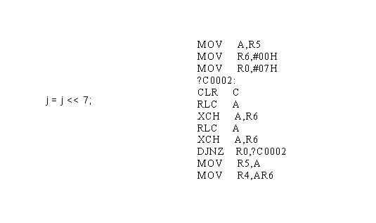
Figure 1 - Example of code bloat
Stage III
FPGA Size Consideration
As part of stage 3, Group A plans to use the XSV 300 board to process the notes of the UMI. They plan to do this by executing a series of steps in parallel on each of the notes. This could lead to problems with space on the XSV.
For one thing, the XSV300 board has 3,072 slices available for use. Assuming that we could use all of these resources on the pipelines, this gives 256 slices per pipe. One stage of this pipeline is the sine look-up table. This is a Core Generator module that has a spec sheet. By looking at the spec sheet, we determined that an 8-bit version would take 50 slices while a 10-bit version will take 157 slices. Group A originally planned on using a 9-bit version. In the worst case, the 9-bit version will be the same size as the 10-bit. This leaves just 99 slices per pipeline for everything else. As the rest of the pipeline includes hardware to perform operations on floating point numbers, this probably won't be enough.
One possible solution to this problem is to readjust stage three so that only one sine look-up table is needed. Look-up tables tend to be fast and it might be possible to put each note through one in series without noticeably decreasing the speed of the process. This has the potential to save 1,727 slices that would have gone to look-up tables for other parts. The same tactic may also work for some of the other portions of the pipeline.
Fixed Point Calculations
Group A included in their design a floating-point accumulator for the purpose of keeping fractional indexes into the sine lookup table. Although floating-point numbers can provide greater precision than fixed-point numbers, we recommend using fixed-point accumulators.
Floating-point addition is difficult to implement with many special cases involving movement of the point. This could lead to big problems because Group A’s method uses overflow to create the cyclic pattern of a sound wave. This requires an additional subtraction of a constant in order to emulate overflow because any floating-point representation of sufficient size to hold the value Group A is using would be able to further move the point, creating the ability to represent very large numbers that are not desired in this application.
Using fixed-point numbers is a reasonable solution to this problem. It handles overflow well because it cannot change the position of its point. It also requires no translation to index the sine lookup table, simply truncate all fractional bits. Figure 2 shows a specific version of the fixed-point process using 16-bit integers. In this case, the accumulator adds its value with the increment to provide the new index into the lookup table. The lookup table ignores the lower 7 bits while indexing, but the accumulator keeps this record to provide a more accurate index for future iterations.
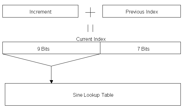 Figure 2 - Example
fixed-point scheme
Figure 2 - Example
fixed-point scheme