How to Build a Creature- CSE-EE-475 (revised 10/9/18)
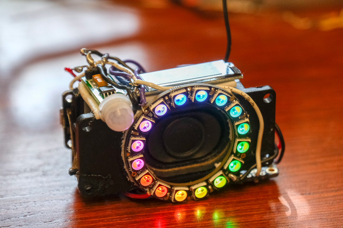
A. Introduction to the Feather M0 processor board
https://learn.adafruit.com/adafruit-feather-m0-radio-with-rfm69-packet-radio
-
Read thru the Overview and Pinouts sections.
-
Skip the Assembly section. DON'T SOLDER ON ANY PINS!
-
Do the Antenna Options section, soldering on a 3” wire for the 915MHz radio on each processor board.
-
Skip to Arduino IDE setup section, and follow the directions to install the correct board packages (some of this may have been already installed).
-
We need the Adafruit AVR Boards and the Adafruit SAMD Boards packages installed.
-
You should not need to install any Windows drivers.
B. Blink
-
Load the Blink example into the IDE and run it. Pay close attention to the Feather HELP! and Adapting Sketches to M0 sections. Don’t go further until your Blink sketch runs successfully.
-
Continue with Using the RFM69 Radio. Download and install the RadioHead library, and load the RadioHead69_RawDemo_TX example on one Feather processor board, and the RadioHead69_RawDemo_RX example on your second Feather processor. You will need a second USB port to power one of the processors for testing.Verify that the radios are working.
-
Read through the rest of this section beginning with Radio Freq. Config, but you don’t need to run any additional examples.
C. Battery
-
-
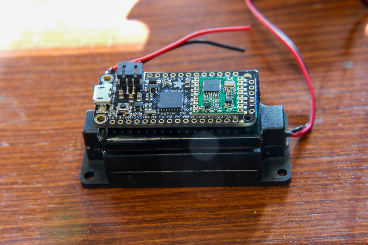
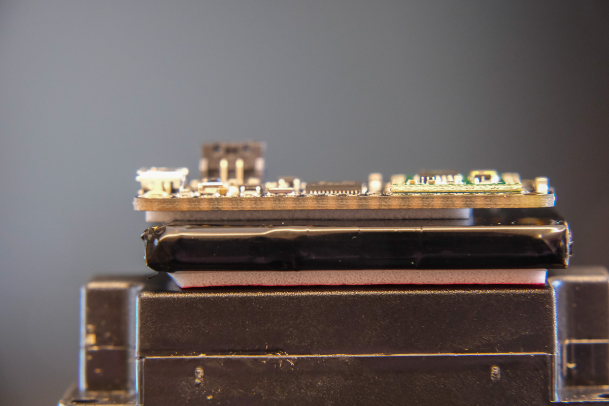
Using the Red foam tape supplied in the lab, affix the Feather processor board to the battery, ensuring that the battery wires are near the USB connector and the black battery connector.
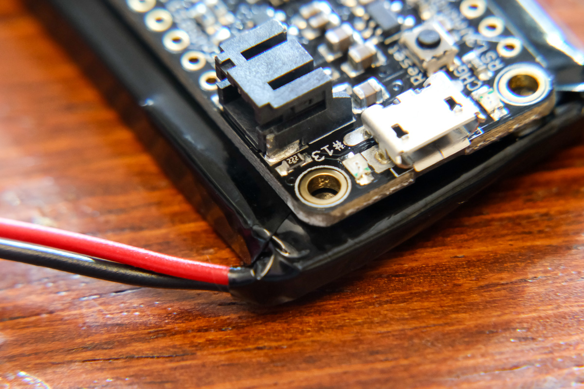
Use one strip of tape down the center of the processor board, so that you can still solder wires to the processor pin holes:
D. Speaker
-
Using Red foam tape, fasten the battery to the speaker so that the speaker wires are at the opposite end from the USB connector. Cut the speaker wire in half, and plug the connector into the battery connector on the Feather processor board.
NOTE: Check the polarity at the battery connector. Black should be nearest to the USB connector. If not, push out the contacts from the connector and reverse them. Or get a pigtail connector from the Lab Staff which should be wired correctly. The battery won't charge if connected backwards!
Find the SPST mini slide switch in your kit, and cut off one of the outside pins. Carefully bend the other two pins up like this:
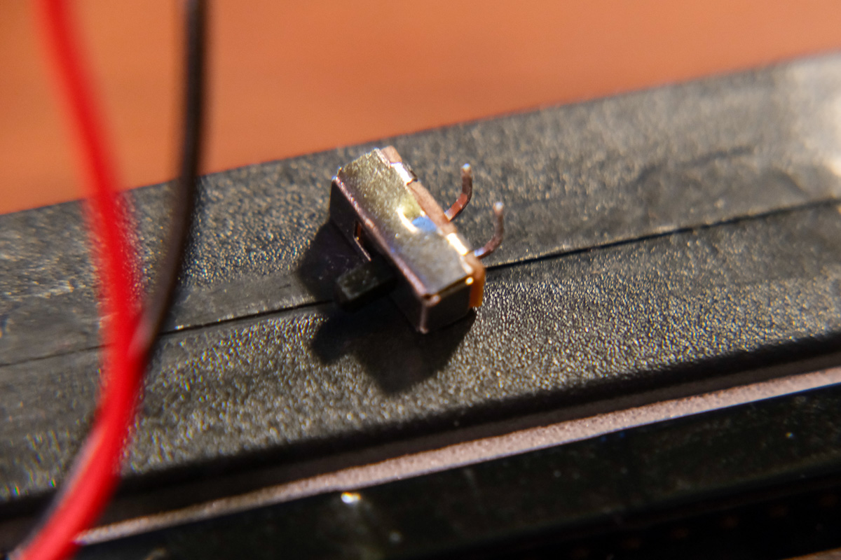
-
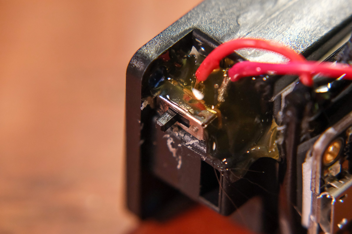
The switch will be hot-glued on the speaker frame in this position:
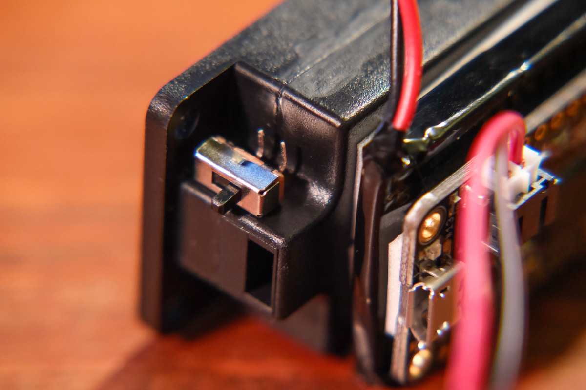
-
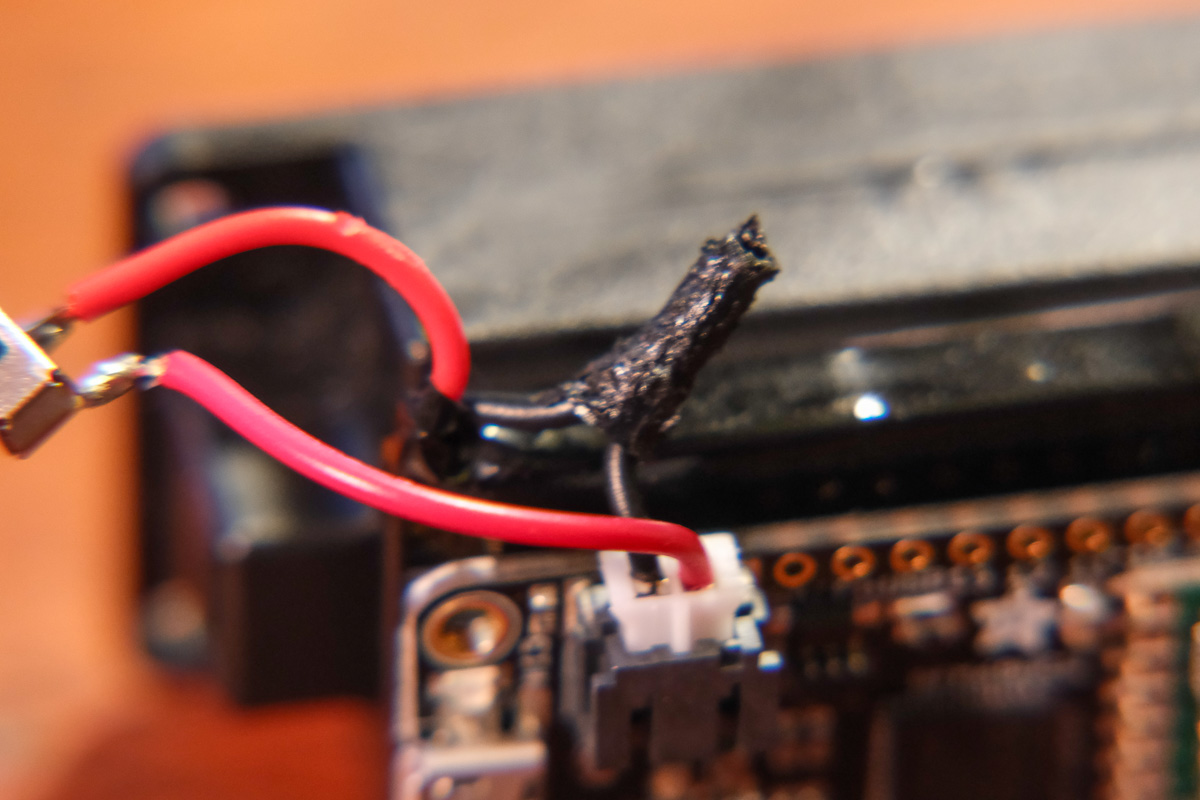
The red wire from the battery and the red wire from the battery connector must be shortened and soldered to the two pins of the switch:
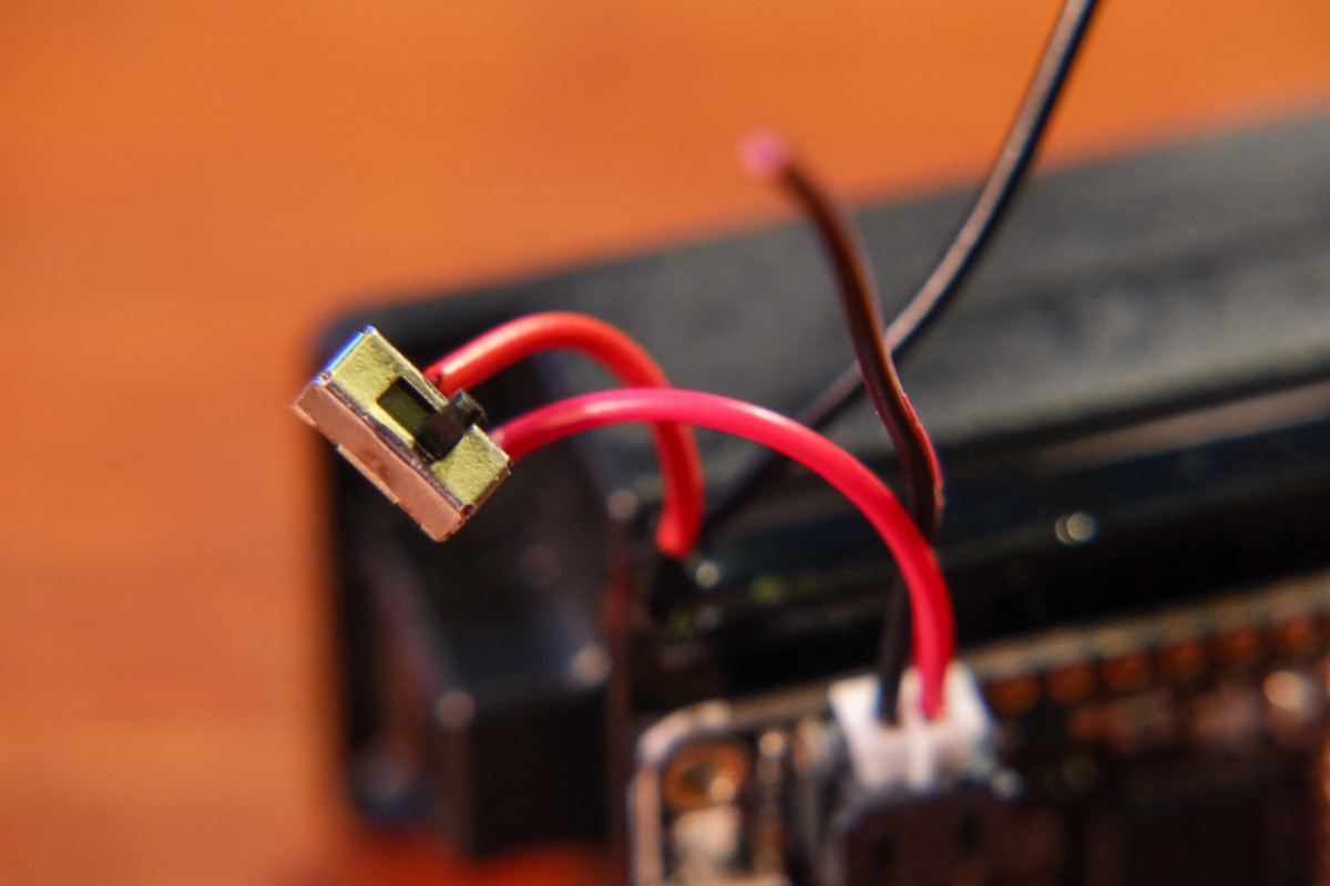
-
The black wires must be shortened and soldered together:
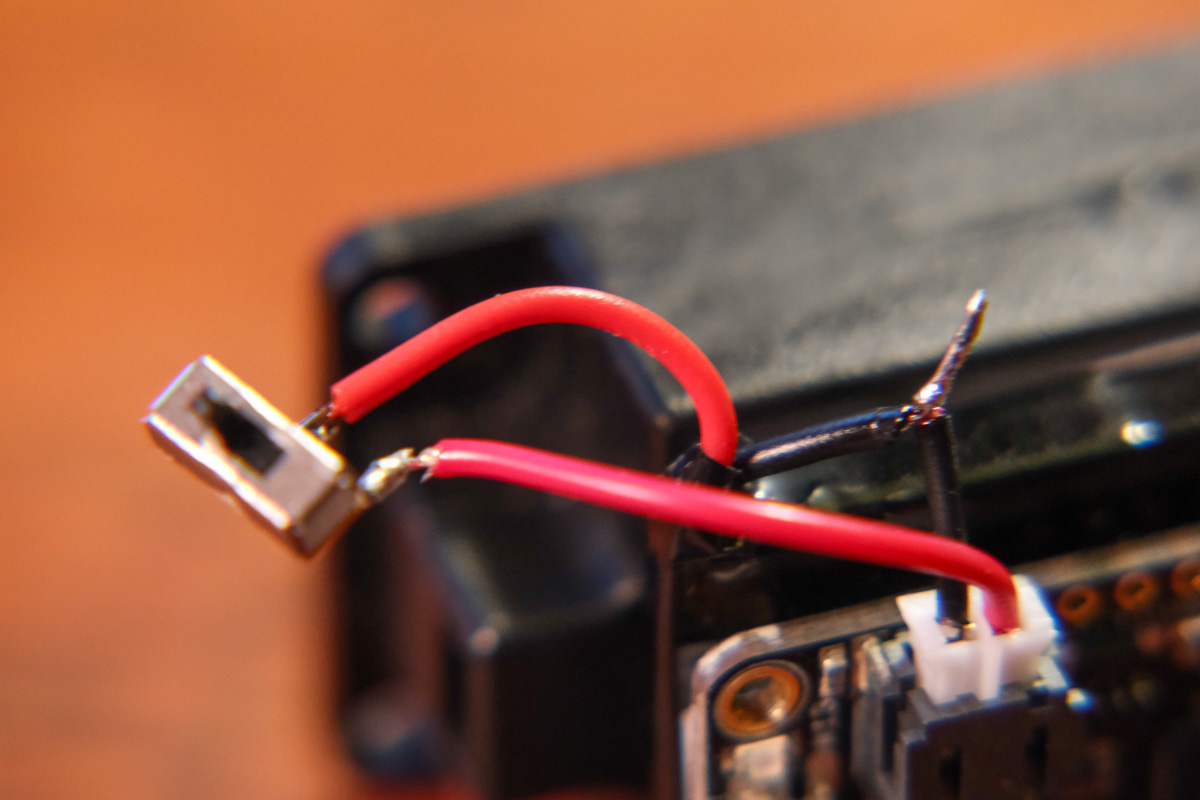
-
The joint should be covered by heat-shrink tubing located on the soldering table. Use your soldering iron to apply heat to the tubing to shrink it tightly to the joint:
-
Use the hot glue gun to apply some glue to the speaker frame to mount the switch:

-
Check your wiring to see if it makes sense: red to red, black to black. Load your Blink sketch in the Arduino IDE and add the battery voltage code so that you can see the battery voltage. Plug everything in and run the sketch. The voltage read will be different if the switch is on or off. In the off position the voltage will be about 4.4 volts (5 v from USB minus a protection diode drop.) When the switch is on you can watch the battery voltage slowly increase as the battery is charging.
-
If the battery voltage is above 3.5 volts, your blink program should still run if you unplug the USB cable.
-
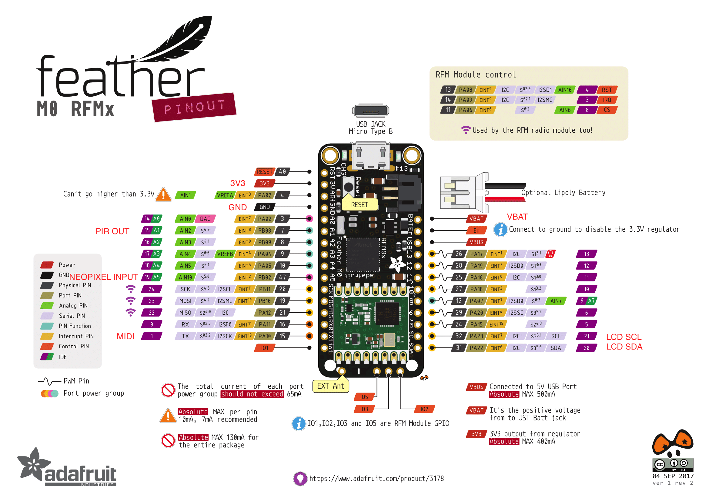
We are going to use three power signals extensively: Ground, 3.3 volts, and VBAT. You should use a specific color of wire for each of these power lines. We suggest Black for GND, Red for VBAT, and White for 3.3V. Other colors can be used for signals. Here is the wiring pinout for the processor board:
E. NeoPixel Ring
The NeoPixel Ring is mounted with foam tape to encircle the speaker diaphragm:
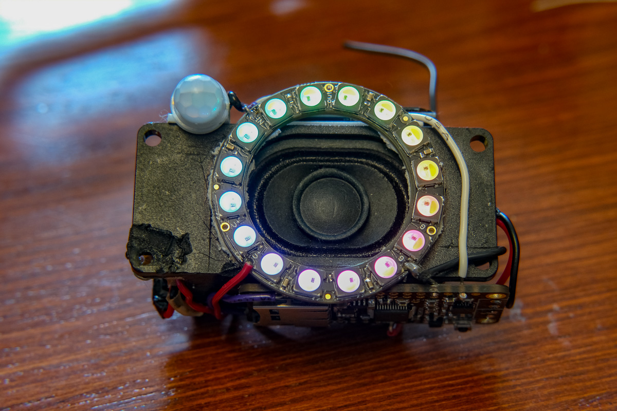
On the back of the neopixel you will see three pads marked “Power 5V DC” (goes to VBAT), “Power Signal Ground (goes to GND), and “Data Input” (goes to A5 on the processor). Solder three appropriate wires entering from the back, about 3” long. Position the Neopixel as shown, and tape it down:
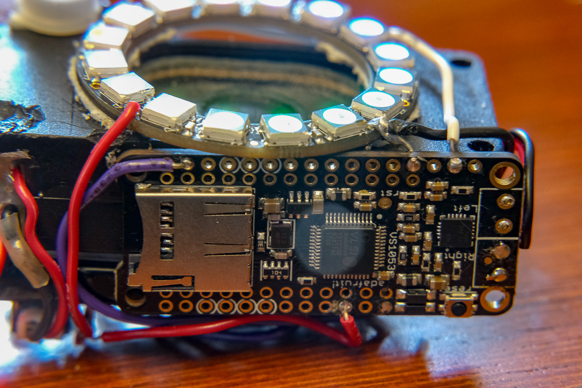
You will need to trim the tape to conform to the Neopixel curve.
F. Music Maker FeatherWing board
Read about it: https://learn.adafruit.com/adafruit-music-maker-featherwing/
Before mounting the Music Maker FeatherWing board you must bridge the pads labeled “G0” and the pads labeled “MIDI” on the back of the board with a bead of solder:
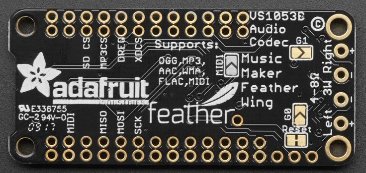
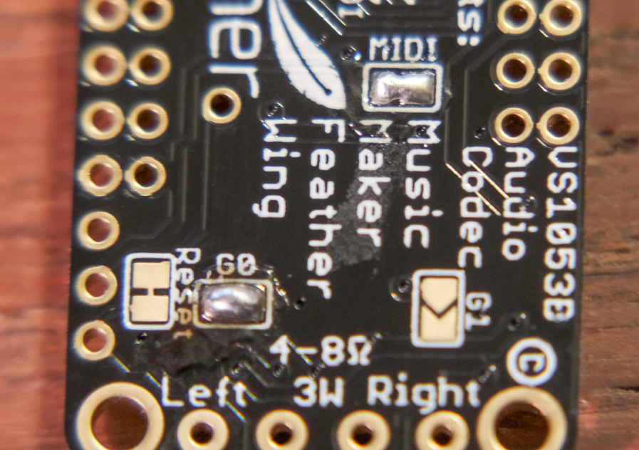
This sets the gain appropriately and selects the MIDI synthesizer instead of the MP3 player.
Mount the board with tape so that the speaker output pads are near the speaker wires, and the end of the board alines with the end of the speaker frame. This allows us to remove the G0 jumper if needed:
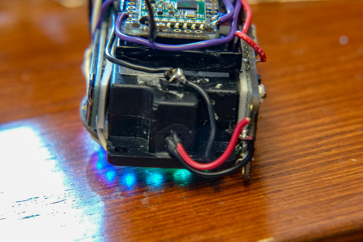

Solder the speaker wires to the Right channel output pads, Red to Plus, Black to Minus. Leave the left channel pads unconnected.
The Music Maker FeatherWing board has three power connections: GND, 3.3V, and VBAT for the amplifier power. In addition, the MIDI input is wired to the TX1 pin 1 on the processor board.
G. OLED display and PIR sensor
The OLED display and PIR sensor are mounted as follows:
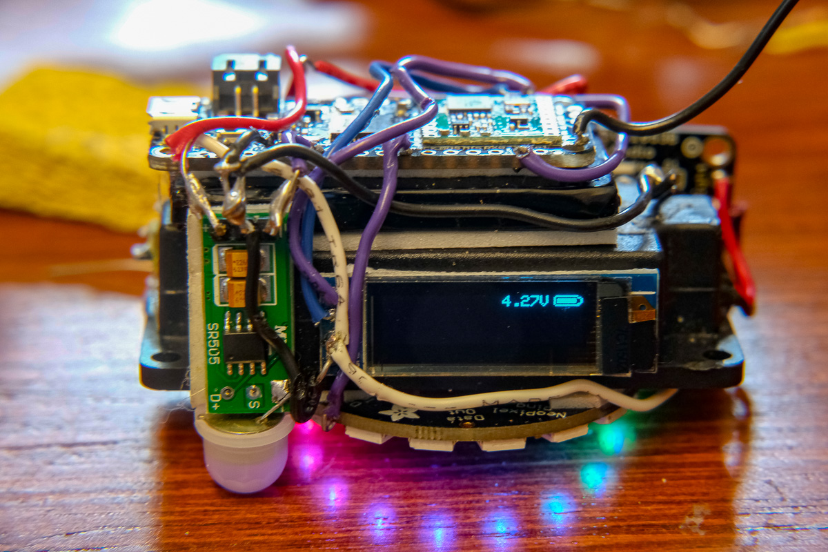
The OLED display connects to GND, 3.3V, SCL and SDA on the processor.
The PIR sensor connects to VBAT, GND, and Output to Pin 15 on the processor. Refer to the processor pin diagram. NOTE: the sample above is wired incorrectly. Output and Ground are reversed. It won't work!
Left to right above should be: VBAT, OUTPUT, GND.
Here is more information on the OLED:
https://learn.adafruit.com/adafruit-oled-featherwing/usage
You will need to install the libraries shown.
H. Wiring and Testing
We suggest that you wire all of the GND (ground) connections first, remembering that the source of the GND the GND pin on the processor. Then add the 3.3V power, followed by the VBAT power.
Then add in all of the signals for each peripheral, one at a time. Keep your wiring neat and tidy!
As you add a peripheral, you can run our example sketches:
Music Maker FeatherWing board: Run this sketch.
NEW: Everything-- Sound, Neopixels, Radio all in one Run this Sketch.


