UW CSE
Autumn 1999
CSE467 Advanced Digital Systems
Design
Instructor: C. Diorio
Homework Set 2
DUE: Oct 15,1999, 9:30 am
Collaboration Policy:
Unless otherwise noted, you may collaborate with other CSE467 students
on the homework assignments. Do not look at homework or exam solutions
from previous years. You must spend at least 15 minutes working on a problem
before seeking assistance. Collaboration means that you may discuss the
problems and make notes during the discussion, but you may not look at
other students' work when writing up your homework. Your homework represents
your own work-the homework must show that you understand the material and
have worked as an individual on every problem. You may not divide up the
task of doing the problem sets in the interpretation of collaboration.
You may discuss lecture material with anyone.
Late Homework Policy:
The weekly assignments are due at the beginning of class. Assignments
handed in after class will incur a 10% penalty; the penalty will increase
by 10% for each additional day late.
Reading:
Review Katz, Chapters 6-7,
Please show all of your work, and remember, your solutions must
be legible. The points for each problem are noted on the problem statement.

-
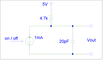
(8 pts) The clock source you used in lab has an open-collector output.
The equivalent looks roughly like above.
The current source turns on when the output should be "0" and turns
off when the output should be "1".
-
Assume the current source is initially on, and turns off at time t=0.
Write the expression for the voltage Vout as a function of time
t.
-
The current source turns back on at time t=20µs. Write an
expression for the voltage Vout as a function of time t.
-
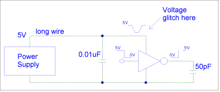
(8 pts) An inverter drives a 50pF load. The rise time of the inverter is
1ns. The power supply is 10ns away (time for current to get from the power
supply to the inverter). The inverter has a 0.01µ F decoupling capacitor
across its power and ground leads. When the inverter output transitions
high, what is the amplitude of the glitch on the power lead? Assume that
all the transient current goes into driving the 50pF load capacitor.

-
(8 pts) Katz problem 6.11.
-
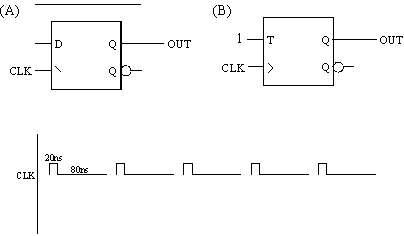
(8 pts) Given the following circuits and a clock input as shown, draw the
timing diagram for OUT in each case. Assume that OUT=0 at time t=0.
Describe the function each circuit performs. What is OUT?s duty cycle if
the input clock duty cycle is (a) 20% (shown), (b) 50%, and (c) 80%? Why
might these circuits be useful?

-
(8 pts) Draw a circuit that asserts its output (active high) for exactly
4 clock cycles every time the circuit receives a COUNT pulse. Assume (1)
that you are given a continuous clock signal, (2) that the COUNT pulse
is exactly one clock period in width, and (3) that COUNT is synchronous
with the clock signal. Design your circuit using edge-triggered D flip-flops
that have synchronous RESETs. Make sure that your circuit's output is free
of hazards (you may find that using an RS latch in your design simplifies
the circuitry substantially). You may not assume that all the flip-flops
have the same delay from clock to Q. Assume that the COUNT pulses are more
that 4 cycles apart.


