CSE467-Lab 6 (modified 2/8/05)
DUE: In one week, at 2:30 pm
 Collaboration Policy:
Unless otherwise noted, your group may collaborate with other CSE467 groups on the lab assignments. Collaboration means that you may discuss the experiments and make notes during the discussion, but you may not copy another group’s work when doing the experiments; you may not copy experimental results from another group; and you may not copy any part of another group’s lab report. In addition, every individual in a group must understand the experiments, must participate in the writeup, and should understand the results. Collaboration does not mean that one person may perform the experiments and another write up the results – all lab partners must share equally in all parts of the lab assignment.
Purpose
You will apply what you've learned about Microblaze and EDK to add a serial port and a waveguide implementation.
Part 1- SRAM-based Sound with the Microblaze and CSE AUDIO board
1. Now take your code from Lab 4 Part 3, and move the sine table to the SRAM. Store it as 32 bit values. Play the scale from #19 in Lab 4 Part 3:
19. Make your sine wave cycle through the following frequencies (200 ms. each):
- 440.00 (A4)
- 493.88 (B4)
- 554.37 (C#5)
- 587.33 (D5)
- 659.26 (E5)
- 739.99 (F#5)
- 830.61 (G#5)
- 880.00 (A5)
The musically inclined of you should recognize this as the A major scale. Demonstrate your output to a TA.
2. Finally, expand your sine table to 1024 entries representing only a quarter-wave. Modify your code to use this quarter-wave table to produce results of a 4k table.
Demonstrate and hand in your working C code that handles the expanded sine table.
EXTRA CREDIT: add linear interpolation to increase the accuracy of your sine routine. Demonstrate and hand in the interpolation code.
Part 2- Adding a Microblaze UART Interface.
- Add the
opb_uartlite serial interface to your microblaze, and connect it to your serial hardware in your UDF file.
You'll probably want to use the low level driver found in
xuartlite_l.h to drive the Microblaze end of the serial connection.
Note that calling XUartLite_RecvByte is a blocking call, so it will not
return until it has received a byte from the desktop. Even though this
blocks the main execution, the audio interrupts will still happen.
- Use the ascii characters "1" through "8" to trigger the eight notes of your scale above.
- Implement an ADSR envelope to control the amplitude of your oscillator. Step through a table of amplitudes to implement this. Use the characters "q","w","e","r" to select a duration of 250 ms., 500 ms., 750 ms., or 1000 ms. Display on the oscilloscope to demonstrate your ADSR envelope.
Demonstrate your routine to a TA.
Part 3- Waveguide synthesis with the Microblaze and CSE AUDIO board
In this lab, you will complete a simple plucked string model using a digital waveguide. When you finish, you should be able to play “plucked string” notes by typing on your keyboard.
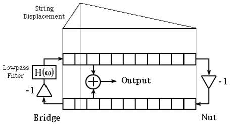
The figure on page 17 in the paper by Smith gives the basic structure of the digital waveguide:
1) A wavetable (at the left, not shown in the figure), provides an initial impulse to the string. When a key is pressed, the wavetable contents are shifted into the delay-line. This can be done easily by adding the output of the wavetable to the feedback from the filter to the delay-line input, or by selecting the wavetable as the input of the delay line. In the latter case, the wavetable should output 0 when it is not plucking the string.
2) A delay-line that models the length (actually twice the length) of the string. The length of the delay-line determines the frequency of the string. You should use a memory, reading and writing one entry per sample time. You can change the length of the delay by using an input that indicates the size of the memory. This can be set to just about anything dynamically. Note that the frequency is now quantized unless you can figure out how to insert a delay of less than one sample!
3) A simple low-pass (FIR) filter provides frequency-dependent dampening. The low-pass filter should look as in the paper, with coefficients of 0.5.
You should experiment with a damping term, e.g. .99, to make the tone die out. You should also check for overflow and “saturate”, i.e. set the result to the most positive or most negative on overflow. You should perform saturation whenever you are performing addition or multiplication.
This doesn't sound very much like a string. Look for hints to improve it in the Smith paper's discussion of Fig. 17, or switch to the model in #2 below, which is the one we'll use next week.
Demonstrate and hand in your working C code that synthesizes the string.
For Extra credit
- Allow notes to overlap so that if a user strikes a key while the previous note is still decaying, it does not get immediately replaced. This is probably most easily done by having a number of delay lines and cycling through which one gets plucked.
-
Create a different method of plucking. Widen the pulse to make it more like plucking a guitar string. What is the effect of changing the PICKUP LOCATION? Can you change it? Maybe implementing this model will help:
- Tinker with the low-pass filter in the bridge reflection. What changes to the sound can you obtain?
Demonstrate and hand in your working C code, with the answers to any questions above.
bruceh@cs