CSE 466 Blimp Project — Final Report
Capt. Dustin A. Richmond Private Eye Alexander K. Horton Robo Tamer Jim Youngquist
1 Introduction
The goal of this project was to give us valuable experience working as a team, while programming the MSP430 platform to integrate separate heterogenous subsystems into a unified whole. The deliverable for this project was a remote-control blimp with a variety of sensors built on the Blimp Bot 1.0 platform. Blimps like this have a wide range of potential applications, including search and rescue platforms, traffic surveilence, and atmospheric research. These applications require directional sensing for movement, basic altitude and direction control for maneuvering and stability, and obstace avoidance in addition to the desired sensor arrays. Using the MSP430F5510 microcontroller from Texas Instruments, the platform we have programmed has all of these movement features, with room for additional sensor expansion.
1.1 Technical Goals
- How to produce a custom SimpliciTI application
- Use the SimpliciTI application to develop an interface for wireless control of the robotic blimp
- Implement a wireless RUN/STOP controller for the blimp
- Control the motors
- Control the IR proximity sensing subsystem
- Develop a PC-side GUI for remote control of your blimp.
- Implement autonomous altitude control using the IR proximity sensor.
- Develop a system to integrate all of the board features
1.2 Intellectual Goals
- Learn how to divide work evenly amongst a group in a way that ensures as little code integration overhead as possible
- Learn how to work with the multichannel timer peripherals on the F5510
- Learn how to control motors using PWM and an H-bridge driver IC
- Learn the theory of IR proximity sensing/ranging
- Learn the inner workings of the various blimp subsystems
2 Hardware:
As metioned in the introduction, this project was designed for the Blimp Bot 1.0 system. Our system used nearly every feature of this board.
Processing and communication was handled by an MSP430F5510 (aka F5510) on the Blimp Bot PCB. This microcontroller was responsible for interracting with all of the blimp features and communcating with a computer base station via the wireless transmitters. The eZ430-RF2500F transmitters consisted of an MSPF2274 connected to a CC2500 and a small Rx/Tx ceramic antenna. These transmitters implemented the SimpliciTI protocol developed by Texas Instruments. Our use of this protocol is covered in the Software section of this report. Communication between the wireless transmitters and their respective endpoints was via a UART serial protocol, running at 115200 baud.
A computer base station was responsible for recieving and recording data transmitted by the blimp, and responding to each data packet with control commands. Control input was provided by either a Sony Playstation 3 (PS3) USB controller attached to the computer or a simple GUI. The PS3 controller inputs were read by the computer, scaled, and then sent to the blimp following each data packet.
The motors on the blimp board were controlled by hardware PWM from the F5510, which were used to drive two LV8405V Motor-driver IC’s. One driver IC controlled the left and right motors, while one IC controlled the vertical motor.
Sensors on the blimp board included rudimentary LED infrared (IR) range finding, 2 electric field (e-field) sensors and a 3-axis compass. The IR rangefinding subsystem used a VB104FASR Infrared detector and 5 SFH4641 Infrared LED emitters. Due to time constraints, we did not use the e-field sensors or the compass.
3 Software and Firmware:
3.1 MSP 430F5510 “Operating System”
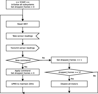
Our F5510 serially loops through five modes of operation; sense, transmit, receive, control, and sleep, see Figure 1↓. The microcontroller executes each of these states at 20 Hz. In the sense state, data is collected from the IR sensors. The transmit step sends collected data to the PC, where it may or may not be processed. Upon receive, the 5510 looks for a command from the PC, usually containing motor control data. The control phase actually enacts the command sent by the PC. Finally, at the end, the 5510 goes to sleep to maintain a 20Hz update rate and conserver power. It is possible to have a higher update rate, but in our experience that wasn’t necessary for control and merely consumes more power. A watchdog timer is also used to ensure uninterrupted service in case an error occurs somewhere during the main loop. Unfortunately such errors occured quite frequently due to apparent instability in the F5510 chip. These glitches were most pronounced when running the F5510 at 16MHz and higher, but were reduced to an acceptable operational level at 12Mhz.
3.2 Motor Control:
The motors on our final project were controlled by the PWM hardware on the MSP430F5510. Due to problems that we encountered when using Timer_A interrupts and UART simultaneously, we only allow variable speed control on the left and right blimp motors, leaving the vertical motor to be controlled by the user. The speed of the motors is set by the function set_motor speed (int left, int right, int vert) in motor.c. Negative integers are mapped to reverse spinning direction, while the magnitude sets the speed. This function takes values from -127 to 127, and sets the corresponding direction and speed for the Left and Right motors. The vertical motor operates in reverse if vert is less than 0 and in forward if vert is greater than 0. If vert is 0, then the vertical motor is in standby mode.
The motor control command is listed in the Appendix: Table 1.
3.3 Wireless Communication and UART System:
3.3.1 SimpliciTI Modules:
Two SimliciTI RF2500 boards were used to create a seamless wireless UART link between the F5510 and the computer base station. SimpliciTI is a packet based protocol and since UARTs are not, we created a simple wrapper protocol around the UART in order to increase our bandwidth on the wireless link. This was necessary because the SimpliciTI chips were programmed to operate at 256K baud and the SimpliciTI protocol has enough overhead such that it isn’t possible to maintain a 115200 baud UART connection for more than a few characters.
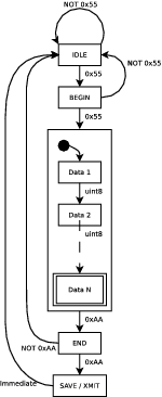
Our UART wrapper protocol transmits 16 bytes of data with 2 bytes for a start sentinel of 0x55 0x55 and 2 bytes for an end sentinel of 0xAA 0xAA, a total of 20 bytes. The sentinel values were chosen for their distinctive binary representation to ease debugging. Wireless transmission is atomic, that is, if there is a communication error in the computer or blimp to RF2500 module, nothing will be transmitted. The protocol is shown in Figure 2↓
3.3.2 Blimp Board 1.0 MSP430F5510 and Computer:
The F5510 and computer have send and receive wrappers around the low-level UART using the same protocol described above. That means all transmissions between computer and blimp are done in packets of 16 data bytes. This size was selected as a tradeoff between amount capacity and speed. 16 bytes is sufficient to transmit all the IR channel readings in a single packet and small enough to allow up to a 40Hz round-trip data rate at 115200 baud.
A simple API for our UART protocol consisting of the functions uart_send_data(uint8_t data[16]), uart_receive(uint8_t buffer[16]) and uart_receive_blocking(uint8_t buffer[16) was created on both the F5510 (in C code) and computer (in python). This has proven to be a convenient abstraction over low level UART communications.
The F5510 does not by default block on receive but instead compares an internal packet count to see if any new commands have been sent since the last main loop cycle. Packet loss can come from either dropped packets on the wireless interface or simply no control program running on the base station. If no new packets are recieved for 5 main loop cycles or more, the F5510 halts all motor operation as a safety precaution. Due to the safe non-blocking nature of the F5510 communications, it is possible to seamlessly connect and disconnect from a computer to test out different sensor filtering and control algorithms.
3.4 Sensor Control:
3.4.1 IR Sensor
For sensing information about its environment, our blimp relied on five on-board IR LEDs and one IR sensor. Four of these LEDs are placed to face in each horizontal direction (front, back, left, right), while the fifth LED is downward facing. The IR sensor has a field of view of 170 degrees, which covers at least some reflected light from each LED.
The F5510 has the ability to select only one LED at a time through a multiplexer, and a single data line to the multiplexor provided the ability to turn the selected LED on or off. The F5510 was also permanently connected to the IR sensor output through one of its analog conversion pins. By multiplexing through each of the LEDs, and collecting measurements with the IR sensor when each individual LED was powered, we were able to get information about object distance to the left, right, front, back and bottom of the blimp.
Retreiving data from the LED-IR sensor system was not as straightforward as turning on an LED, and reading the voltage at the analog input pin, or even turning on the LED and taking the average of multiple readings for that matter. Since proper sensor data-based control relies on the purity of the data, it was necessary to also mask out any potential IR interference. In order to do this, we used the following steps, which can be repeated as many times as desired (we repeated 64 times):
- multiplex into the LED and set its power to off [LED = 0]
- set an accumulator to zero [acc = 0]
- sample the value at the analog input channel [samp = ADC]
- if the LED was off durring the sample, switch the sign of the sample [if LED : samp = -samp]
- accumulate the value [acc = acc + samp]
- toggle the LED pin state [LED = !LED]
- Goto 3
Note that this algorithm uses sample->set, which provides the maximum possible time for the reading on the IR sensor to adjust to the current LED settings. Using this method, we were able to cut down on noise (although the channel was still very noisy), and therefore had better responsiveness to our blimp’s environment. Accumulation also extends the effective detection range of the IR sensor. 64 samples enabled us to detect objects up to 4 feet away, depending on the size of the object.
After acquiring our sensor data on the computer, we wanted to linearize it in order to have finer-grained control over the blimp when it was very-near some object or obstacle. Taking readings from the bottom LED at various distances, we were able to reconstruct how the values changed with respect to the distance from a target. In our case, we found that a quadratic approximation (in distance to sensor reading) matched our data to an acceptable extent.
3.4.2 E-Field Sensor
Initially we wanted to include the optional e-field sensor in our blimp, but unfortunately ran out of time before we were able to complete the addition. We did make some design choices which would have allowed the very easy adoption of the e-field sensor. The only actual difference between an e-field sensor, and the IR sensor (at least from the microcontroller’s perspective) is whether samples should be taken using sample->set or set->sample. While our IR sensors simply required that we take samples after exposing them to our desired light level for as long as possible, e-field readings need to be taken so that they coincide as closely with the maximum and minimum responses as possible.
3.5 Final Application and GUI:
We created our gui using python and it’s gui package Tkinter. Using our gui, we could control the blimp motors, send start/stop commands, and read sensor data. However, we did not have enough time to integrate the height control we originally wanted to implement as part of the gui. Height control is implemented as a separate library.
Our gui has 13 buttons. Ten buttons are dedicated to movement and motor control. One button stops the blimp (STOP), one sets the desired height (not implemented in the gui, implemented elswhere), one switches to PS3 (Not implemented in the gui).
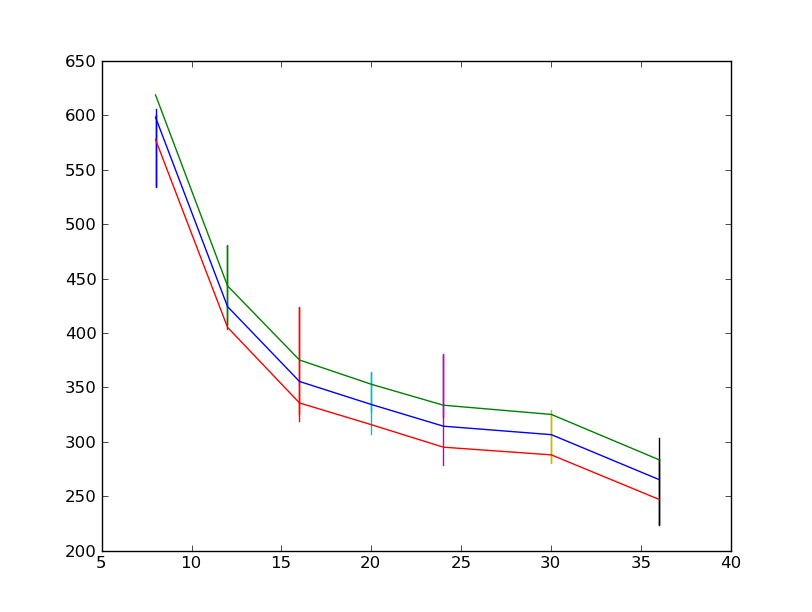
Finding an equation to map non-linear analog data to linear range values was done in several steps. First, Jim collected 200 samples at 7 points: 8 inches from the bottom sensor, 12 inches, 16, 24, 28, 32, and 36 inches. The data for each point was averaged, which created the table below.
| Average analog value | Distance(inches) |
| 598.105 | 8 |
| 424.275 | 12 |
| 355.465 | 16 |
| 334.305 | 20 |
| 314.39 | 24 |
| 306.615 | 30 |
| 265.27 | 36 |
The full collected data is plotted in Figure 3↓. Vertical bars indicate maximal range seen over 200 samples. The 3 slopping lines indicate mean and plus/minus 1 standard deviation. It is interesting to note that the standard deviation is about 20 over the entire range of readings, which translates into less absolute error for nearby objects, due to the nonlinearity of the IR sensors.
3.6 Extra Functionality:
3.6.1 PS3 Controller
We used pygame to interface between our PS3 Controller and our microcontroller. Get information about pygame at www.pygame.org.
3.6.2 EField Sensing
Efield sensing is discussed in the Sensor Control section.
4 Results and Analysis:
The IR system proved to be very noisy, and was not precise enough to have accurate altitude control. We were pleasently surprised that the rf2500 module was able to communicate at a greater line of sight distance than expected. As-advertised it can communicate at 20 ft, but we were able to control our blimp from halfway across the CSE atrium.
5 Discussion:
Our first, and most complicated challenge that we encountered was setting the F5510 clock frequency, and the subsequent problems related to the clock speed and UART settings. Initially, we wanted to run at 20 MHz to maximize the amount of calculations we could do on the microcontroller. However, we discovered that when MCLK is at or above 20 MHz, the USCI_A UART Serial hardware ceases to send, or recieve data. At 16 MHz we were able to achieve UART Rx and Tx functionality, but the code did not execute correctly for a variety of reasons. First, we discovered that the microprocessor would exit infinite loops. An example of where this happened behavior is in Figure 4↓ where the F5510 program counter would, seemingly randomly, be set to 0x0002 or 0xFFFF.
In the example of Figure 4↑, correct execution would execute until line 3 in the code above until rx_hd != rx_tl. However, after several malfunctions and debugger sessions, it became obvious that our microprocessor was leaving the while loop when rx_hd==rx_tl.
We discovered that running the clock at 12 MHz almost completely eliminated the problem. However, running at 12MHz still did not relieve a problem that we had seen at 20 and 16 MHz. If Timer A interrupts are enabled to implement the vertical motor software PWM, while Rx and Tx interrupts are enabled for UART send and receive, there are certain occasions where the interraction between the two interrupts cause the program to hang because the program counter jumps to an infinite loop at a random address, or a null address at the bottom of the heap. Both of these addresses cause the program to hang, and we were unable to find a solution that allowed timer A1 and the USCI_A UART to coexist peacefully.
6 Improvements
A few ideas for improving the blimp board are now given. The layout on the PCB could be rearranged so that there is better coverage of the downwards facing IR LED. This LED is arguably the most important since it is used for height control. Currently, the vertical motor and RF2500 chip block much of its illumination. An alternative to an IR LED for height sensing is to use an IR laser and small/cheap camera to do ranging, see https://sites.google.com/site/todddanko/home/webcam_laser_ranger for an example. Processing of the camera data could be done on an FPGA with an I2C interface to the F5510.
Finally, more powerful motors would be great. We found that in many cases, especially for vertical control, the current motors are particularly anemic.
7 Conclusion:
We are happy to conclude that our project was a success. Our final product met all of the project requirements set in the introduction in the process of controlling and running our blimp platform.
We also learned many valuable lessons in the course of our project. First and foremost, it is imporant to do research beforehand to choose a system that is both adequate for your needs and is well supported. In some cases, the MSP430 was not an ideal platform; We found bugs in the development environment, as well as in the MSP hardware.
However, we overcame these bugs, and learned from our experiences. We now move forward as more informed engineers, and we will work to avoid these problems in the future.
8 Appendix:
All command packets are preceeded by the start sentinels, and followed by the end sentinel. The command packet itself is comprised of a 1-byte opcode and 15 bytes of arguments/data.
Table 1:
| Opcode | Meaning | Data |
| 0 | All Stop | None |
| 1 | Motor Speed | u16 left, right, vertical |
| 2 | User message | u8 *msg |
| 3 | Sensor data | u16[5] IR readings |