In this lab you will learn how to interface with the sound board we will be using to create the Flock project. The goal of this lab is for you to gain an understanding of how to generate sound using the Yamaha chip.
This is a 3 part lab. In it, you will:
| Name | JP3 Pin | Connects through | Connected To | ||
| GND | pin 1 | >> | -- | >> | GND |
| YCOE | pin 2 | >> | 1K resistor | >> | ATmega16 pin 33 (PA7) |
| YRST | pin 3 | >> | 1K resistor | >> | ATmega16 pin 35 (PA5) |
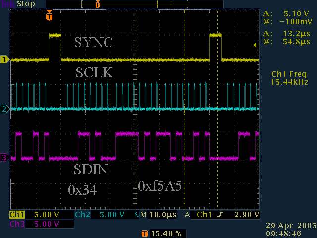
| SDIN | pin 4 | >> | 1K resistor | >> | ATmega16 pin 17 (PD3) |
| SYNC | pin 5 | >> | 1K resistor | >> | ATmega16 pin 20 (PD6) |
| ExtV | pin 6 | >> | -- | >> | +5Volts |
| SCLK | pin 7 | >> | 1K resistor | >> | ATmega16 pin 18 (PD4) |
| IRQ | pin 8 | >> | -- | >> | ATmega16 pin 16 (PD2) |
| MPWM | pin 9 | not connected | |||
| GND | pin 10 | >> | -- | >> | GND |

Here is a sample birdsong in text format:
// \Birdsongs\btwa.mid
mthd
version 0 // single multichanneltrack
// 1 track
unit 100 // is 1/4
end mthd
mtrk(1) // track 1
/* U0 */ /* 0ms */ trackname "BTWA.MID"
/* U0 */ /* 0ms */ text "created from WAV file by WAV2MID (C) Tanager Productions"
/* U0 */ /* 0ms */ beats 120.00000 /* 500000 microsec/beat */
/* U0 */ /* 0ms */ program ChoirPd
96; /* U96 */ /* 480ms */ +f#7 $64;
6; /* U102 */ /* 510ms */ -f#7 $00;
27; /* U129 */ /* 645ms */ +f#7 $64;
17; /* U146 */ /* 730ms */ -f#7 $00;
24; /* U170 */ /* 850ms */ +f#7 $64;
31; /* U201 */ /* 1005ms */ -f#7 $00;
38; /* U239 */ /* 1195ms */ +f#7 $64;
27; /* U266 */ /* 1330ms */ -f#7 $00;
/* U266 */ /* 1330ms */ +f7 $64;
4; /* U270 */ /* 1350ms */ -f7 $00;
/* U270 */ /* 1350ms */ +d#7 $64;
10; /* U280 */ /* 1400ms */ -d#7 $00;
/* U280 */ /* 1400ms */ +d7 $64;
17; /* U297 */ /* 1485ms */ -d7 $00;
/* U297 */ /* 1485ms */ +d#7 $64;
7; /* U304 */ /* 1520ms */ -d#7 $00;
/* U304 */ /* 1520ms */ +f#7 $64;
10; /* U314 */ /* 1570ms */ -f#7 $00;
/* U314 */ /* 1570ms */ +g7 $64;
4; /* U318 */ /* 1590ms */ -g7 $00;
/* U318 */ /* 1590ms */ +f#7 $64;
3; /* U321 */ /* 1605ms */ -f#7 $00;
/* U321 */ /* 1605ms */ +g7 $64;
4; /* U325 */ /* 1625ms */ -g7 $00;
/* U325 */ /* 1625ms */ -c-1 $00;
/* U325 */ /* 1625ms */
end mtrk
MIDI unit position and time position are shown in comments before each command:
/* U7765 */ /* 34085ms */
Comments are inside /* ... */ or start with // till end of line.
Pauses are shown before commands either in MIDI units ( 47; )or musical notation ( 536/4; ).
MIDI notes consists of pairs of commands: Note on is displayed as + and Note off is displayed as -
MIDI channel are displayed in mtrk(channel number) or as [channel number] inside a track before a command.
Values are shown decimal (0-127) or hexadecimal ($00 - $7F).
Hint—use the lines with – notes (note off events); the first value is the number of milliseconds of duration of the event, in 5 millisecond steps.
Standard MIDI file format is here.
2. Using the above sample and hints and the yamaha data sheet information on notes, convert the note information in bpwa.txt into notes that are playable on the Yamaha chip. (Extra hint: Compare bbwa, which is the converted song in Yamtest-Sample.c with the bbwa.txt file).
Question 1: If a note is in octave block 2 and the timbre uses a muliple of 2, what register values would you have to change in order to shift the note up two octaves?
Question 2: Without changing individual notes, how would you double the amount of time to play a song?
Question 3: The Yamaha chip uses a FIFO interrupt to tell the controller when to send more note data. How would you configure the Yamaha chip to interrupt when its FIFO is half empty?
Part 4
· Each song is stored separately.
· You should be able to play the 16 birdsongs (from your MIDI conversion above and the others provided) and select them by a button
· One button selects which birdsong (displayed as 1-16 in hex). If a song is currently playing and this button is pressed, you do not need to be able to interrupt the song being played change to the new song (but the next song you play should be the new song).
· One button is start/stop. You should use the Decimal Point on hex LED display to display when your birdie is in running mode. It should be on when running, off when stopped.
· The displayed song will continually play until the stop button is pressed or the song to play is changed.
For all files turned in, the comments at the top of the file should contain:
Be prepared to answer questions about the Yamaha sound chip and interface during grading.