CSE466 Lab 6: “Radio Communication”
Objectives
The goal of this lab is to write a module for TinyOS and gain some experience with radio communication and sensor networks. In this lab you will learn the following:
- The major concepts used in TinyOS programming
- TinyOS networking basics
- How to create your own TinyOS module
- How to build and use test fixtures
Important Warnings
- DO NOT power the mote from the AC adapter and batteries at the same time. ALWAYS turn off the mote’s battery power before placing it in the programming board. Only one mote should be plugged into the MIB510 programmer.
- Be careful when placing your mica2dot into your MIB510 programmer - do not bend the pins.
Important Notes
1) The types of motes you will be using in lab are the "mica2" and "mica2dot". Make sure to compile your program for the correct piece of hardware. (e.g. 'make mica2' NOT 'make mica') For mote programming you will be using the MIB510 serial programming board.
2) Use your new lab partner number (from the lab partner assignments page - for the second group of labs) as your group number in hex. Please make sure to type in your group number as a hex number.
3) The mica2 and mica2dot are built around the ATmega128 microcontroller not the ATmega16. Register names may vary slightly.
4) Use the default radio frequency and programming board. If you don't specify the radio frequency or programming board it will automatically choose a correct value.
5) Make sure your MOTECOM variable is properly set when trying to communicate to the devices over serial. The mica2 communicate at 57600 baud while the mica2dots communicates at 19200.
Resources
TinyOS
Tutorials
ATmega128
datasheet
avr-gcc manual
nesC 1.1 Language Reference Manual (in course pak)
DLP Design – DLP-2232M Module Datasheet (in course pak)
FTDI Chip – FT2232C Application Note (in course pak)
Application
notes section for the AVR 8-bit RISC family
Suggested Steps
PART 1:
In this part of the lab, you will be using a java app called Surge.
Surge is an example application of sensor networks that periodically samples a sensor (e.g., light or temperature) and reports the readings to a base station. Surge uses ad-hoc multi-hop routing over the wireless network to deliver samples to the base station.
Surge motes organize themselves into a spanning tree rooted at the base station. Each mote maintains the address of its parent and its depth in the tree, advertising its depth in each radio message (either sensor sample or forwarded message) that it transmits. A node selects an initial parent by listening to messages and choosing the node with the smallest depth; to seed the creation of the spanning tree, the base station periodically broadcasts beacon messages with depth 0. Nodes estimate parent link quality; when the link quality falls below some threshold, nodes select a new parent from their neighbor set based on link-quality estimates and depth. Once a second, each mote samples its light sensor and sends the sample to its parent. Parents acknowledge received packets. Surge uses the acknowledgments to provide a reliable transport layer; parent link quality is calculated as the fraction of transmitted messages that are acknowledged. When a node receives a message from another node, it forwards the message to its parent. Sensor samples are collected at the base station where they can be analyzed or visualized
Surge has an accompanying java program for displaying the multi-hop routing topology.
For help on Surge, see:
http://webs.cs.berkeley.edu/tos/tinyos-1.x/doc/multihop/multihop_routing.html
1. You'll need to work with other lab groups so that you have
more than two motes. Team up with two or more other groups so there will be 3+
or more groups working together.
2. Choose a group number for Part 1 for all the motes in your big group. The group number should be a group number of one of the lab groups that joined the big group. That way we avoid two larger groups using the same number. NOTE: For the other 2 parts of the assignment you should use your assigned group number to not interfere with other groups.
3. Program your motes with the Surge application ( in /cygdrive/z/apps/surge). Be sure to use a single unique group ID during the installation, but each mote needs a unique node ID. The base must be node 0. Leave the node 0 mote on the programming board to communicate with the java visualization tool. All nodes have the same code but the node with an ID of ‘0’ acts as the base and should be connected to the programming board. Node IDs are programmed by the command "make install.N mica2dot" where N is the node ID.
4. Deploy
your nodes. You may need to place some nodes outside 003 and/or bend the antenna to limit strength to get multi-hopping to
work. The default range on the nodes has a large distance.
5. Run surge with the
command:
'java net.tinyos.surge.MainClass
<GroupId>'
where <GroupId> is the
group number used when compiling the motes’ application.
6. Once surge has loaded, press "Start Root Beacon" button to get things started.
Question 1: Provide a
graph of the node topology you were able to obtain. What did you have to do to get a 2-hop
network? A 3-hop network?
PART 2:
In Part 2 of the lab you will complete the last part of the “Ball Lightning” project by making your control system adjust a light over a wireless network. The motes will act as a wireless switch and/or light. You will need to add the MoteConn class to SPI/USB control to send mote packets to the SerialForwarder provided in TinyOS.
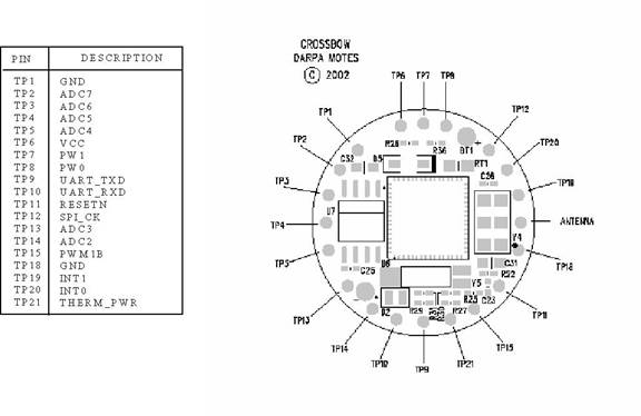
1. Attach an LED to the mica2dot between TP15(PWM1B) and TP18(ground).
2. Create a new folder in your apps directory for your solution to part 2. In this folder you will want to create your application files and a dimmer module (HPLLEDDimmerM.nc) to control the PWM. Your application should consist of a configuration file (LightNode.nc) and a module (LightNodeM.nc) that receives radio packets, parses the light value from the radio packet, and sends the light value to HPLLEDDimmerM.nc to output the correct brightness. You will also need to create an interface(LEDDimmer.nc) to issue commands to your dimmer module. NOTE: Leave all files in your application directory as the compiler will look in the local directory first before moving on to tos/system, tos/interfaces, tos/platform, and tos/libs. This will avoid problems with files being deleted when you log off.
3. Implement your LED dimmer module (HPLLEDDimmerM.nc) in TinyOS using Timer 1 of the ATmega128. Output your PWM signal on PWM1B. NOTE: Timer 1 is a 16-bit timer and the ATmega128 may use slightly different register names than the ATmega16. You may want to use the 8-bit PWM mode so that it's similar to the Lab 4 implementation.
4. Write your LightNode application that receives the desired light level from the radio (use AM message type #33) and updates the level of brightness of the LED attached to the mote.
5. Modify your SPI/USB code to use the MoteConn class to transmit the desired light level in a TinyOS radio packet with AM message type #33. The light level being sent over the radio should be controlled by your accelerometer. MoteConn is a simple class that opens up a connection to the TinyOS SerialForwarder and allows you to send packets. MoteConn needs to link to ws2_32.lib. Instructions on how to link MoteConn to ws2_32.lib in MSVC are provided in MoteConn.h. Here is the MoteConn Files
SOMETHING TO CONSIDER: We could have easily created a small
handheld
Question 2: How many
different AM message types can you have?
What would you change if you needed to have more types than the maximum?
PART 3:
In Part 3 of the lab you will create a sensor network that collects light level readings from surrounding nodes and adjusts the brightness of its LED based on the surrounding light readings. You will need to implement nodes that will perform two primary objectives: 1) Take periodic light readings and send the reading over the radio and 2) Receive light readings from the 20 closest neighbors, calculate an average light level, and update the LED brightness based off the average light level. Unfortunately, you do not have enough motes to test/demonstrate your sensor network so you will need to build a test fixture to verify that your code works.
- Implement
the first objective of your application by taking light readings every
second and transmitting the 8 most significant bits of the
NOTES:
1) If all messages are coming from the node connected to the PC simulating the other nodes they will appear to all be the same distance away; therefore, the signal strength should be included in the packet.
2) We are recommending that you simplify packet parsing by using one byte in the payload/data section for the sender address. (Even though TinyOS uses 16-bit addresses)
- Implement the second objective of your application by obtaining an average of the 20 closest light readings being sent over AM message type #20. Use the result of the calculation to determine the brightness of the mote’s LED. Feel free to reuse the HPLLEDDimmerM.nc you created in Part 2 to control the LED brightness.
- A simple test fixture system has been provided that will allow you and your partner to design specific test scenarios to help debug your system. The testing system takes as an input file with specified test packets that it will process and send out over the radio. Here is the test fixture tar file. Please refer to the “README” file for more information on how the system works. The system was developed by one of the previous 466 TAs to help students design and debug sensor networks. Please inform the course staff of any bugs you find as future students will most likely continue to use the system. For this quarter we have already added a LightSensorPacket type that matches the specifications form Part 3 of this assignment. An example test file called “LightSensorTestFile” has been included.
Question 3: What
other testing utilities could you think of providing for sensor networks? What capabilities would they have?
Deliverables
For all files turned in, the comments at the top of the file should contain:
- Both partners' full name, login and student number.
- The lab number and the part of the lab (e.g. “Lab 6, Part 2”).
- Demonstrate Part 1 working
to a TA during lab. No turn-in
is required.
- Demonstrate Part 2 and Part 3 to a TA during the first half and
hour of the next lab.
- Turn in hardcopy of your
commented nesC code for both Part 1 and Part 2.
- Make sure to follow TinyOS conventions
- Turn in at least one of
your test scripts from Part 3 with an explanation of why the test scripts
prove your program works correctly.
- In the explanation we will be checking to see that you thought about how to test to ensure that your program meets all the requirements
- Turn in your answers to questions 1, 2, and 3.