Tech Description
![]()
The
Nintendo Controllers:
In this proof-of-the-concept project two Nintendo controllers are attached to a circuit board (and will probably be a little cumbersome to use). Nintendo controller uses an 8-way parallel to serial converter (4021 IC chip) to transport the current state of the buttons and eight-way directional pad. More info on a Nintendo controller and 4021 IC could be found on the following web site: http://www.gamesx.com/controldata/nessnes.htm
The five important pins of this chip used in the project are:
POWER—powers the chip (+5V DC)
GROUND—grounds the chip
PL (parallel load)—latches the input on high-low transition (falling edge).
DATA—serial output of 4021 IC
CLOCK—used to clock out the serial data.
The main part of the project involved getting information from the Nintendo controllers. To do this, the simple routine called readPads() (see thumbpad.c) was used. It first signaled the parallel load, and then toggled a clock line for both controllers, reading in the data as it came in. From there it was just a matter of decoding the inputs and sending the appropriate value to the serial port of a PC. You can find the pinout for the standard PC serial port in the following web site: http://vbmhome.cjb.net/ Next follow the schematics and source code of the project, as well as some further thoughts.
Key
Mapping:
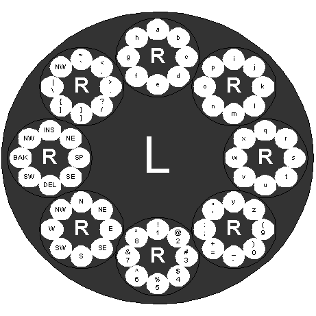
The following figure shows how to type using our two 8-way directional controllers. The large circle represents the left controller, and the small circles represent the right controller. For example, if you would like to type the letter ‘c’, you would press the left controller in the up direction, and the right controller to the right. For a space, you press the left controller to the left, and the right controller to the right. In our implementation, the ‘A’ button on the left controller works as the shift key. This gives capital letters, or the raised symbol in the diagram below. In our implementation there are several keys, which have not yet been programmed. These keys are denoted by their direction (i.e. ‘N’, ‘E’, ‘NE’, etc.) These keys could be programmed as macros that type commonly used words, such as ‘the’, or your name.
