

|
The Infamous Servo Controller Bug The servo controller routine, comprising a paltry 150 lines of code took an inordinately excessive amount of time to write due to an elusive bug that prevented the servos from operating correctly. This is the summary of what the bug was, and what it took to stamp it out. I should start by saying, in my own humble defense, that finding and correcting the bug was made more difficult due to several factors: The description of the problem was simply that the servos would not work. This was frustrating because the general idea was very simple. Just send out timed pulses, 1 to 2 ms long, every 20 - 30 ms. I had decided on writing the routine for 8 servos because if I was already writing it for 2, 6 more wouldn't take any more time to code. The Motorola chip has 10 "official" I/O lines, but (for those of you counting) I was using 8 for the servos, and needed 3 for the serial I/O. I accomplished this by using the IRQ input line as a general I/O line, accessed by two special instructions. What was the problem? Was the host (Atmel) chip not sending the proper serial data? Was it the routines in the Motorola chip that were wrong? I didn't know at first, so I tried to narrow the problem down to one of the two chips. If the serial data was OK, then I would assume the problem would be in the Motorola servo driver routines. The best way to answer which chip was the problem would be to look at the serial data being sent across the 3-wire interface. So, I connected up the labs' Tektronics logic analyzer to the three wires. This showed that the serial data seemed to be coming across just fine. 16 bits were being transmitted, with the proper data format, and the Motorola chip seemed to be ACK'ing each bit as it arrived. Ok, so now I figure it has to be the routine in the Motorola chip. The question was, was it the timer routine that actually pulses each of the servos in turn once each 32 ms? Is it the serial interface routine that gets each bit from the host? Was it the command routine that took the serial data and manipulated it into pulse width values? Well, I looked over each routine with a fine tooth comb, traced each step, and even simulated each routine on the simulator, but they all seemed to work properly. Although it only took one sentence to say, it took several days of simulating, reviewing, re-writing and re-burning the chip to actually accomplish. And still the servos would not work properly. After looking and looking, I started to piece a bit of the puzzle together. I had noticed that the servos exhibited a strange property. Commands sent to servo #2 or servo #3 seemed to be appearing on the servo #1 line. Not only that, but when the servo was commanded to turn as far as it could go CW, the servo would only actually turn about 1/2 way. Hmmmm, very strange... Finally, I started taking a good close look at the logic analyzer traces. Yes, they did indicate that all 16 bits were being transmitted and acknowledged, however, there was always this strange delay between the 15th and 16th bit ACK pulse. At first I didn't give it much thought, it was only a little longer, and the ACK pulse spacing varied a little anyway. But what was strange was that it was always there, no matter what data I sent, or which servo I sent it to. This turned out to be the key bit of information I needed that made all the other things fall into place. I tried to figure out what could cause these three strange behaviors, and if they could all three be explained by the same problem, and then it hit me. 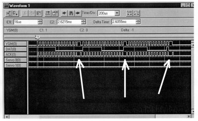 The logic analyzer shows peculiarities in the signal. The Motorola chip's serial I/O routine is designed as a 4-way handshake with the host. As soon as it gets all 16 bits that form a complete data package, it goes off and does whatever command it just got. Well, if it thought it had 16 bits, but really only got 15, that would explain everything! It would explain why commands for servo #2 were showing up on servo #1, because the address pattern, which was supposed to be 010 for servo #2 or 011 for servo #3 would look like 001, which is servo #1's address (if the last bit hadn't gotten shifted in). It also explained why when the servo was commanded to turn all the way CW, it only turned about 1/2 way. That's because a full CW rotation requires FF for the data value, and a 1/2 way rotation is 80. If the last bit was dropped, an FF would look like a 7F, which is very close to 80. As for the delay in the ACK between the 15th and 16th received bit, that would be caused by the routine executing the command after the 15th bit, and the command instructions would cause a delay prior to returning that was longer than the other ACKs. Aha! It was finally all in place. A simple little routine that had taken many times more days that it should have was finally solved... Or so I thought. I had now narrowed the bug to the serial I/O routine in the Motorola chip, a routine only 24 instructions long. No problem, right! Wrong! I went through that routine countless times. I traced each and every instruction. I simulated each instruction. I simulated for 16 bits, and every time, it worked! It was receiving exactly 16 bits, as it should, before going off and doing a command. And when it had done a command, it was resetting everything just fine to get the next 16 bits. So what was going on here? I started to doubt my conclusions, and whether the other routines were really operating properly. All looked like gloom. I was at the point of blindly substituting other counter values for the serial I/O routine. I tried 17, and that didn't work. 15 didn't work either. It had to be 16, and it had to be that the routine was exiting after getting 15 bits, because that would explain all the behavior I was seeing. But it didn't explain why the routine was written perfectly but still didn't work. So what could explain this? Well, the one thing that the simulator didn't simulate was the timing of the YGM line pulse. A 4-way handshake interface can be quite tricky when there is no framing error control, and in this routine there was none (due to time & I/O line constraints). I asked myself what would happen if right after powering up both chips, the Motorola chip happened to start running it's program first? Aha! That's it! Of course! Anyone could see it! If the Motorola chip came out of reset first, it would begin looking at the YGM line. If the YGM line was high, then it would assume that the first data bit had arrived, and go get it. Unfortunately, if the Atmel chip hadn't come out of reset yet, it wouldn't have had time to pull the line low (which is supposed to be the initial level for a "no-data" state). So the Motorola was getting this first bit in error, assuming it was valid. It WAS correctly counting 16 bits, but the Atmel had only really sent out 15 so far. In this type of protocol, once you're off by 1 bit, you're always off by 1 bit. Of course, this would be a horrible routine to use for reliable data communication, and could be improved with framing error control. I put in a delay loop of approx. 0.4 seconds for the Motorola chip, to ensure that the host chip has time to get its lines straightened out before it starts to look at the YGM line. The moral of the story is that simulators can't tell you everything, pay attention to every little strange thing you notice about your program's behavior, Always use framing error checking, and thank heaven for logic analyzers! |
December 2000 - Matt Cosand, Kevin Nichols