|
CSE 464 - Character Pre-Production for 3D Animation |
||||||||||||||||||||||||||||
Assignment #4: Gray ModelingThe overall goal of this assignment is to convert your multi-piece block model into a single gray model. Parts 1-3 will be more on the technical side, guiding you in combining your multiple block models into a single gray model. Part 4 is where you get to be more artistic, trying out different things, adding detail as needed, and sculpting things to look right. When creating the gray model feel free to bring in any extra reference if it helps you, such as images of the construction lines or sketches of the character in various poses. Resources
|
||||||||||||||||||||||||||||
Joint |
Name |
Orientation |
Directions |
Pelvis |
center_root_bind_joint |
Orthogonal to world space |
Unparent the root joint from the skeleton and unparent its children. In the Attribute Editor: Rotate should be 0, 0, 0 and Joint Orient should be zero or multiples of 90. When finished, parent the joint back into the skeleton |
Chest |
center_spine_3_bind_joint |
Orthogonal to world space |
[the same as above] |
Head |
center_head_1_bind_joint |
Orthogonal to world space |
[the same as above] |
Elbows, Knees |
right_lowerarm_bind_joint, right_lowerleg_bind_joint |
Coplanar to shoulder, wrist |
In the Attribute Editor: Translate should be 0 on Y and Z, but X can be non-zero. Rotate and Joint Orient should be 0 on X and Y, but Z can be non-zero. |
Hands |
right_hand_bind_joint |
Inline with lower arm |
In the Attribute Editor: Translate should be 0 on Y and Z, but X can be non-zero. Rotate and Joint Orient should be all zeros. |
Feet |
right_foot_bind_joint |
World space, rotated coplanar to leg |
Translate should be zero on Y and Z, but X can be non-zero. |
- First, unparent the feet. We need to keep the rotate value in the channel box. If we freeze the transform without unparenting the foot, the rotation gets pushed into Joint Orient, which can cause problems when translating the foot IK control on the Control Rig.
- Select the root joint
- Freeze Transforms: Modify → Freeze Transforms
- Parent the feet back to the skeleton
Part 3: Combine the Block Model into a Gray Model
The next stage is combining all of your block models into a single piece of geometry. The overall strategy will be to combine two pieces at a time, adding extra edge loops to get the same number of vertices where the blocks will combine. Most often there should be 8 vertices on the edges that need to be combined. (with the exception of 6 for the fingers).
You will only need to work with one side of the block model at this stage. Any changes or combining you do will just be mirrored over at the end.
- Unparent all block models from the skeleton then hide the skeleton.
- Tear off the menu for Isolate Select. In the viewport menu go to Show → Isolate Select and click on the dotted line at the top.
- Do the following for each pair of blocks that have a matching number of vertices on each end. If the numbers do not match up you will need to modify the geometry by adding edge loops such that they do. See "Special Cases" below for some guidance on how to accomplish this for certain pairings.
- Select a particular block, turn on View Selected
- Delete faces on the end of that block
- Toggle off View Selected, repeat for the adjacent block
- When each end is clear, select both objects then shift right click and go to Combine.
- Merge vertices using one of the three methods:
(via shift right clicking and going to Merge Vertices)
- Merge To Center
- Merge Vertices
- Note: behaves like Merge To Center if only 2 are selected
- When selecting vertices that you intend to merge be careful not to unintentionally marquee select ones behind them
- Merge Vertex Tool (welding)
- When finished merging two pieces it is generally good practice to delete history. Working without deleting history for too long can drastically slow down your scene. Go to Edit → Delete All by Type → History.
- Special Cases:
- Neck to Chest
- Prepare to merge the chest geometry to the neck by inserting two edge loops down the chest.
- Raise the center four faces, delete them, and use the hole to join up to the neck.
- Note that this will also create two additional loops down the front and back of the chest, so the spine sections below will also need these additional loops.
- Prepare to merge the chest geometry to the neck by inserting two edge loops down the chest.
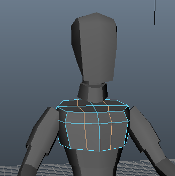
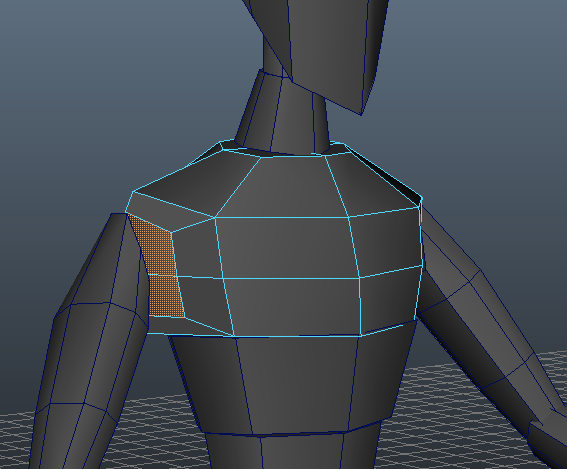
- Chest to Shoulder
- Add a vertical edge loop to the bottom half of the chest
- Extrude the four faces on side of shoulder scale them in to match the width and height of the shoulder.
- Delete extruded faces so there's a hole
- Merge vertices after combining with shoulder geometry
- Merge Vertices to Center is recommended for each set of vertices (so they average)
 Tip: Be careful not to extrude and forget! This can leave behind overlapping edge loops. It is good practice to immediately edit the geometry you have just extruded, either by using the default tool or by immediately switching to the translate or scale tool.
- Neck to Chest
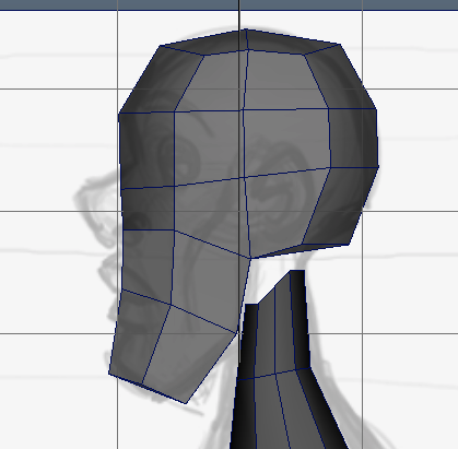
- Head to Neck
- Add geometry to match the concept art more closely (no more than about x2 more geo)
- The jaw should be defined in the back, so don't connect to neck directly to it. As with the chest/shoulder connection, extrude, scale in, then connect.
- Average out the features of the face. Don't go down the slippery slope of adding too much detail.
- Pelvis to Legs
- Add an edge loop so there's enough vertices to match the ends of the legs.
- Extrude faces and scale in.
- Delete extruded faces.
- The shape may be a bit odd looking, but the most important point at this stage is the topology. You'll be sculpting and smoothing out these rougher areas in the next part.
- Add an edge loop so there's enough vertices to match the ends of the legs.
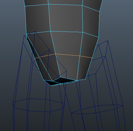
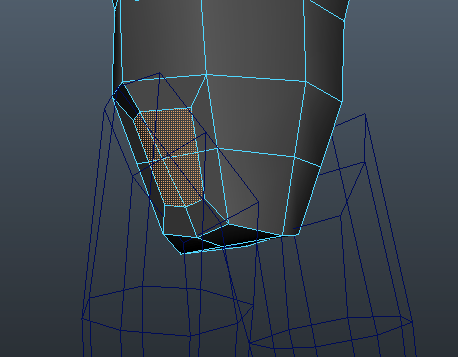
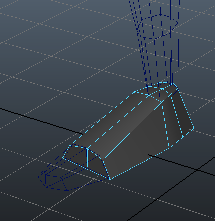
- Leg to Foot
- Add an edge loop around the heel so that the leg can connect to the foot
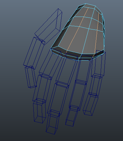
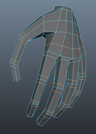
- Hand to Fingers
- Add the following edge loops around the hand.
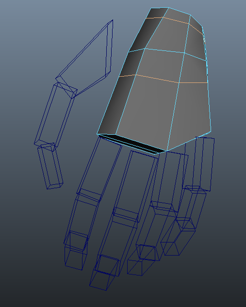
- In object mode, right click and go to Split → Split Polygon Tool. In the tool options you may need to adjust the snapping tolerance. Split the edges down the hand as shown up to the wrist. The "n-gons" (5 or greater sided polygons) you end up with are generally bad, but they will be fine for now.
- Extrude each set of 2 polygons out to create attachment points for the fingers.
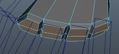
- Extrude out geometry to form the attachment point for the thumb
- Before merging fingers you'll need to add an edge loop to create six sides and match up with the hand. The thumb with need two loops to create the eight sides it will need to match up to the hand.
- Now shape the fingers and merge the geometry together. You may find it easier to shape the finger segments and roughly match the attach points BEFORE combining the pieces of geometry.
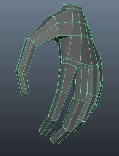
- Finally, add the indiciated edge loops around the knuckles.
- Mirror the geometry
- Once all of the pieces are connected on one side, you can mirror all this work you've done over.
- Delete any unused block models on the other side.
- Select the faces on the side of the character you didn't modify and delete them. This should result in a clean cut down the middle of the character.
- Make sure the vertices down the middle are centered on the axis. From the front, select the line of vertices down the middle. With the move tool, hold down x for grid snapping and translate the X axis to the center.
- If not all of the vertices are snapping to the center line, you may need to uncheck "Retain component spacing" in the Move Tool options.
- Select the object, shift right-click and go to Mirror Polygon → Mirror +X. If you modeled on the opposite from the demo you'll want to select Mirror -X.
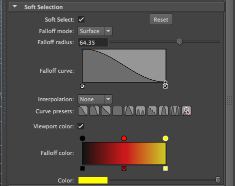
- Finish up by softenening the edges (as you did with the head earlier), and deleting history
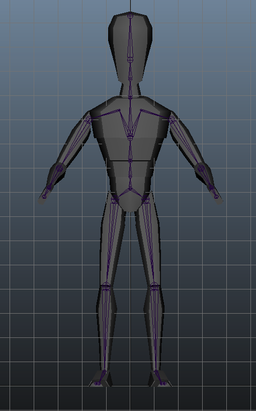
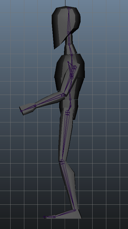
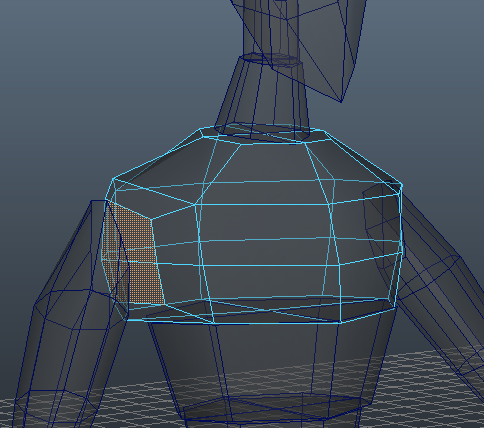
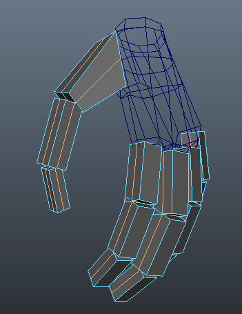
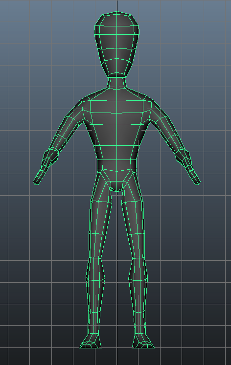
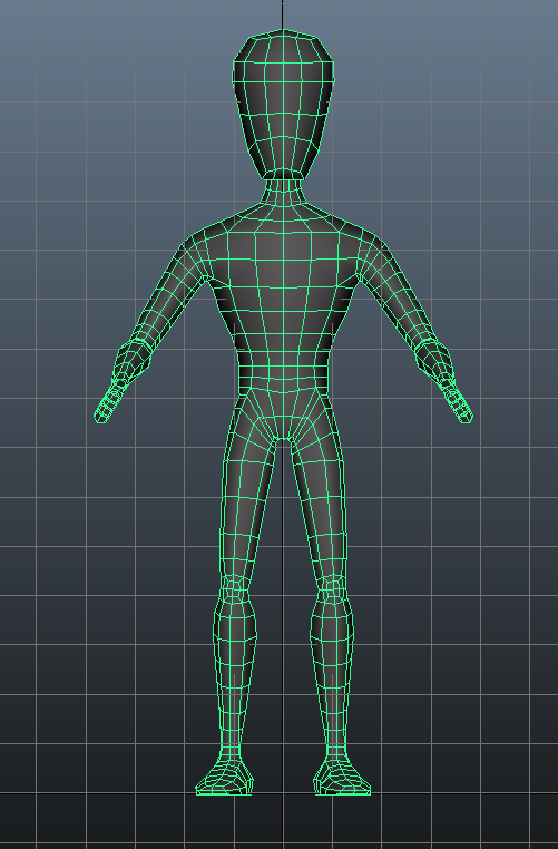
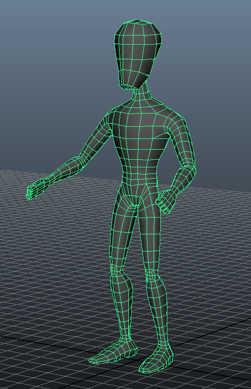
 in the viewport shelf to show wireframe on shaded objects. This enables you to see where the edges are without having to select the objects. You might find this helpful when trying to spot where vertices need to line up between block models.
The initial version of your gray model should look something like this:
Now it is time to add and sculpt in more detail.
Before moving any further, save your file as assignment4_initial_gray_model.ma for turn-in, then save it as another file
named assignment4_gray_model.ma and continue working from there. Additionally, use your initial gray model file to check in with the TAs.
Part 4: Add Detail and Sculpt
The first few parts of this assignment were more on the mechnical side, helping you combine your block models in a way that resulted in a gray model with good mesh topology. This part is a bit more freeform and aesthetic. The number of edge loops you'll add depends very much on what your character needs. It's about refining the silhouette, and sculpting your geometry to make it look like the concept art.
Be sure to model as you go. Don't just drop in all your edge loops at once and sculpt them later. As soon as you drop in an edge, hit r for scale to add in a bit of shape.
And as you're adding edge loops make sure to check that the gray model is still lining up with the skeleton.
With that, go ahead and start refining your gray model! Here are some key parts of the body to look out for:
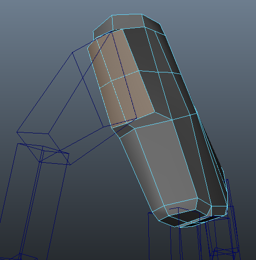
- A couple of edge loops on the shoulder, enough to form out the curve
- An edge loop in center of upper arm and forearm
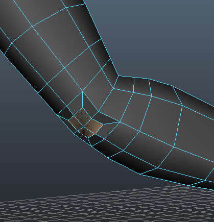
- Flank the elbow with edge loops for further definition

- Extrude the faces in at the elbows to add in a bit of a sharp bend (do this after adding in enough edge loops)
- Be sure not to leave them as is. Shape them so they look natural and not squarish.
Tip: Select the vertices that form the elbow, then shift right click and go to Average Vertices for a quick and easy way to round out the geometry.
- Edge loops to form out the chest and abdomen
- More edge loops to define the knee
- Extrude faces in at the knees like you did with the elbow
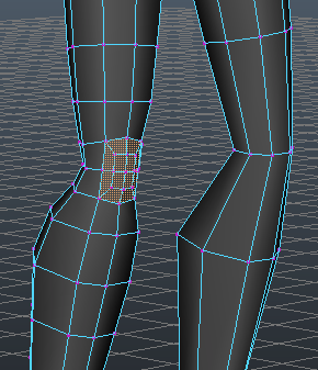
- More edge loops to define the ankle
- Note that sometimes it may not be an issue of adding more, but of using what you have more effectively
- Add an edge loop across the foot for better vertical definition, a couple down the foot
- Add an edge loop vertically down the chest
- Be sure to sculpt in muscles where you can, don't leave leave limbs looking like "macaroni"
Once your topology is in, the Sculpt Geometry tool may be helpful. Hold down b and drag to change brush size. Edit the opacity to affect how strong the brush is. Use push, pull, smooth, and relax to sculpt the model. The model must be selected in Object Mode.
- Pull: Raises vertices from the geometry.
- Push: Lowers vertices into the geometry.
- Smooth: Smoothes out the mesh but the geometry will change the model shape by quite a bit.
- Relax: Like the smooth tool but it tries to preserve the shape of the model while averaging out the vertices.
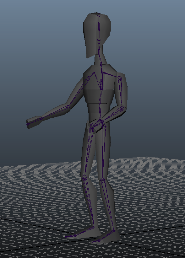
After you're done with your gray model mirror the geometry again so that it is symmetrical.
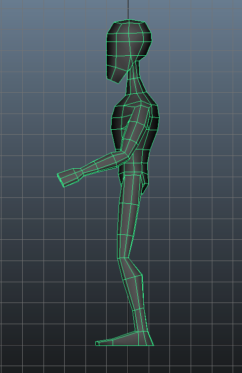
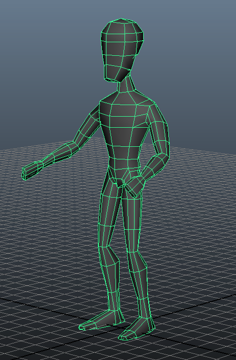
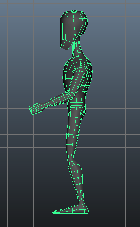
The final version of your gray model should look something like this:
Turning in your files
Like last time you will be turning your files into Collect-It on catalyst. For this assignment, turn in the following:
- assignment4_initial_gray_model.ma (Part 1-3)
- assignment4_gray_model.ma (Part 4)
- Any additional reference images you used
Your assignment is due Thursday 8/20 at 5:00 PM.
In addition, you will be required to check in with the TAs during office hours at least once for this assignment. Make sure to check in with your assignment4_initial_gray_model.ma file.