Assignment #2: Creating the Skeleton
Resources
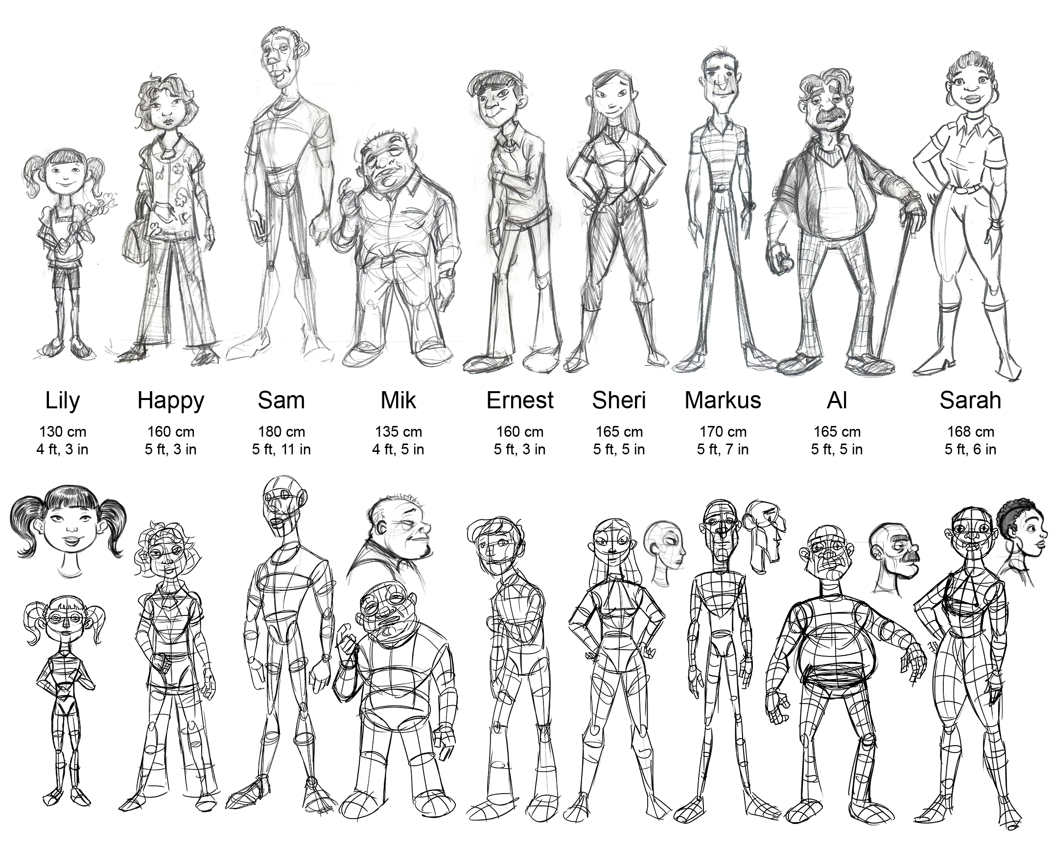
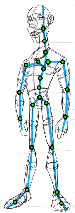
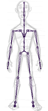
- Character lineup with construction lines and heights (click for a bigger image):
- It is not required for this assignment, but if you want to install the CharacterDesign shelf in Maya, go to the Windows start menu, paste the following path into "Search files and programs", and hit enter:
O:\unix\projects\instr\production1\install_capstone_shelves.py
A window will pop up indicating that the capstone shelves have been installed. Now when you load Maya in the lab a series of shelves containing tools used by the animation capstone will automatically update (This class will only use the CharacterDesign shelf). Note that if your profile does not save you will have to repeat the above step each time you log in.
The only tool currently available is the fader as shown in class. This allows you to select one or more mesh objects in Maya, like your image planes, and create a slider that will adjust the transparency.
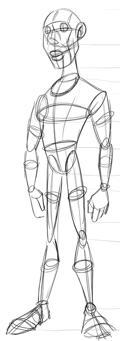
Joint Placement Reference
Joint Tool - (Animation menu set) Skeleton → Joint Tool
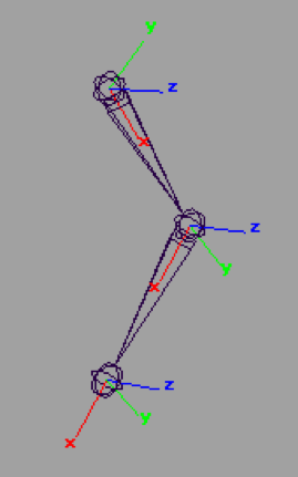
Conventions for joint orientation
Axis |
Orientation |
Why |
X |
Points down toward the child |
Maya auto-orients joints this way as a convention. This minimizes gimbal lock problems when using the default rotate order. However, there are a few special cases where joints in character rigs should be oriented differently. |
Z |
Primary axis of rotation |
Using Z as the primary axis of rotation further reduces risk of gimbal lock. This helps IK work more reliably. |
Y |
|
Rotating the Y axis 90 degrees causes gimbal lock. We try to minimize gimbal lock by orienting Y as the least used axis. |
1. The Back
Click and draw the back joint chain using the Joint Tool. Use the image for reference on where to place the joints. Most characters will need four joints in the spine (excluding null joints). Having four joints makes it possible to create an s-curve. Note: the final deformation skeleton may end up having many more than four joints.
1a. Creating the back joint chain
- Switch to the side camera view
- Activate the joint tool - Skeleton → Joint Tool
- Start with the pelvis. Place the pelvis joint slightly below where the belt would be.
- Next, place the spine 1 through 3 similar to where they are in the reference image. There should be a slight curve to these joints, a relaxed posture. Horizontally, they should be placed slightly more toward the back.
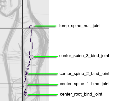
- Finally, place the end null joint directly above spine 3. Press "enter" when finished.
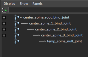
- In the Outliner, click the "+" next to center_spine_root_bind_joint to expand the hierarchy.
- Name the joints as shown in image
1c. Delete the temporary null joint
- Select temp_spine_null_joint
- Press the "delete" key on the keyboard
2. The Neck
Click and draw the neck joint chain using the Joint Tool. Most characters need three neck joints (including the head, but not the end null joint) so that it can bend into a c-curve.
2a. Creating the neck joint chain
- Switch to the side view camera
- Activate the joint tool - Skeleton → Joint Tool
- Place the neck 1 joint slightly below the collar line.
- Place the neck 2 joint in the middle of the neck. Horizontally, it should be slightly more toward the back of the neck.
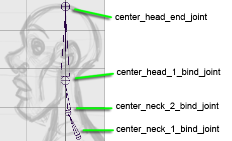
- Place the head joint just below the ear where the vertebrae would join the skull.
- Place the head end null joint directly above the head and press "enter".
- Name the joints as shown in the image.
2b. Parent the neck to the back
- Select center_neck_1_bind_joint
- Shift-click center_spine_3_bind_joint to add it to your selection
- Press "p"
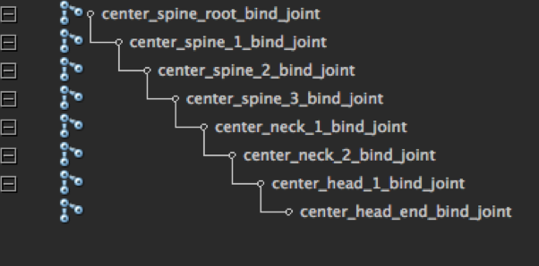
The skeleton should now look like this in the Outliner
3. The legs
Click and draw the leg joint chain using the Joint Tool. Even if the reference image shows straight legs, add a bit of bend to the knee to indicate the direction it will bend.
3a. Creating the leg and toe joint chains
- Switch to the side view camera
- Activate the joint tool - Skeleton → Joint Tool
- Place the hip joint first.
- Place the knee and ankle joints. (knee should be bent, not straight)
- Place the final foot null joint where the heel touches the ground. Press "enter" when finished.
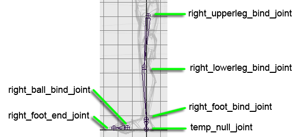
- Create a second joint chain for the toe. Start by placing the right_ball_bind_joint.
- Place the foot end null joint and press "enter" when finished.
- Name the joints as shown in the image
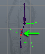
3b. Orient the foot joint in world space
- Unparent the foot joint
- Select the right_foot_bind_joint
- Press "shift-p"
- With the foot joint selected, press "ctrl-a" to bring up the Attribute Editor.
- Zero out all of the joint orient values
- Parent the foot back to the knee
- Select right_foot_bind_joint
- Shift-select right_lowerleg_bind_joint
- Press "p"
- Delete the temporary foot null joint
- Select temp_null_joint
- Press the "delete" key on the keyboard
3c. Parent the toe to the foot
- Select right_ball_bind_joint
- Shift-select right_foot_bind_joint
- Press "p"
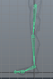
The leg joint chain should now look like this
3d. Align the right leg in the front view
- Switch the the front camera view.
- Select right_upperleg_bind_joint.
- Press "w" to activate the Move Tool.
- Move the joint over on the X axis to align with the reference image.
- Press "e" to activate the Rotate Tool.
- Rotate the Y axis to align with the image.
3e. Parent the upper leg joint to the back
- Select right_upperleg_bind_joint
- Shift-select center_spine_root_joint
- Press "p"
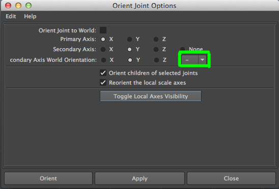
3f. Mirror the right leg to the left side
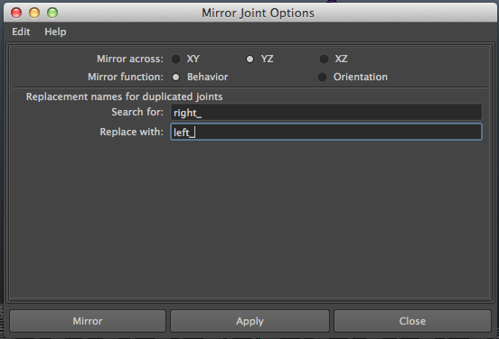
- Skeleton → Mirror Joint (option window)
- Change the settings to match the screenshot below
- Mirror across: YZ
- Mirror function: Behavior
- Search for: right_
- Replace with: left_
- Select right_upperleg_bind_joint and press apply
4. The arms
Click and draw the arm joint chain using the Joint Tool. Even if the reference image shows straight arms, add a bit of bend to the elbow to indicate the direction it will bend.
4a. Creating the arm joint chain
- Switch to side camera view
- Activate the Joint Tool - Skeleton → Joint Tool
- First, place the upperarm shoulder joint
- Next, place the lowerarm elbow joint (elbow should be bent, not straight)
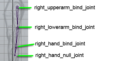
- Place the hand joint
- Place the temp hand null joint and press “enter” when finished
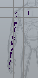
4b. Align the arm joint chain in the front view
- Select right_upperarm_bind_joint
- Press “w” to activate the Move Tool
- Move the joint to align the character’s right arm
- Press “e” to activate the Rotate Tool
- Rotate the joint chain to align with the image
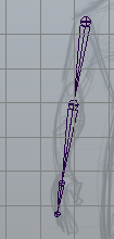
The arm skeleton should now look like this:
4c. Creating the clavicle joint
- Switch to front camera view
- Activate the joint tool - Skeleton → Joint Tool
- Click and draw the clavicle as shown in the image. Press “enter” when finished.
- Name the clavicle joint right_clavicle_bind_joint
4d. Parent the clavicle to the chest
- Select right_clavicle_bind_joint
- Shift-select center_spine_3_bind_joint
- Press “p”
4e. Orient the clavicle joint relative to the chest
- Select right_clavicle_bind_joint
- Press “ctrl-a” to bring up the Attribute Editor
- Zero out all joint orient values
4f. Parent the arm to the clavicle
- Select right_upperarm_bind_joint
- Shift-select right_clavicle_bind_joint
- Press “p”
4g. Mirror the arm from right to left
- Skeleton → Mirror Joint (option window)
- Change the settings to match the screenshot below
- Mirror across: XY
- Mirror function: Behavior
- Search for: right_
- Replace with: left_
- Select right_clavicle_bind_joint and press apply
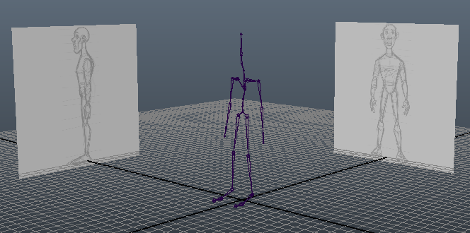
The finished skeleton should look similar to these screenshots:
End of Assignment 2.
Turning in your files
Like last time you will be turning your files into Collect-It on catalyst. For this assignment, turn in the following:
- front_view.png
- side_view.png
- assignment2.ma
- Make sure to use Maya 2012
- Turn in a Maya ASCII file, not Maya Binary
Your assignment is due Thursday 8/8 at 5:00 PM.
>> Assignment 2b from Tuesday's lab <<
|