UV Editing Exercise
The process of texturing involves using an image to apply various surface attributes to a model such as color or shininess. This may seem a bit strange, since an image is 2D while a model is 3D. To overcome this problem, we must provide an explicit mapping between the two dimensions. This mapping is called the UV map. A UV is a coordinate in the 2D image space that is associated with a vertex in 3D. Sometimes there is a one-to-one mapping between vertices and UVs, but it can also be the case that a vertex can have many UVs.
Observe the default UV map of a cube below. You can see the UV map of an object by selecting it and going to Window → UV Texture Editor. Notice that while a cube only has 8 vertices, this UV map has 14 UVs. The UV map does have some features in common with the 3D model. Faces are preserved and some — but not all — of the faces that touch in the model also touch in the UV map. You can use regular camera controls to pan and zoom in the UV Texture Editor.
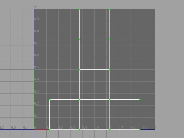
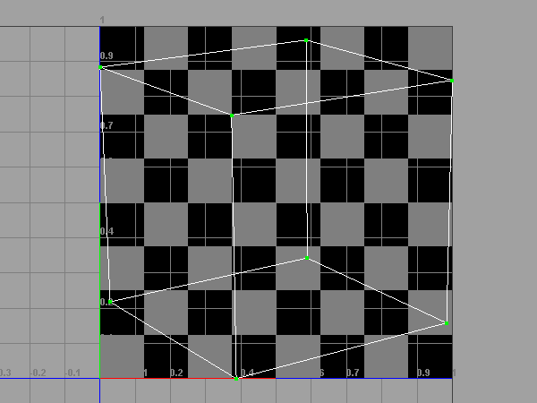
The cube's UV map looks like it could be folded into the 3D model. This is a nice property, but will not always be the case. Below is another UV map of the same cube. This time none of the faces are connected, the faces overlap, and the size of a face is not proportional to its size in the 3D model. This shows you the flexiblity you have when creating a UV map.
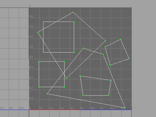
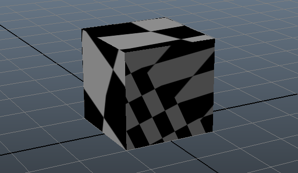
Tweaking UVs without a texture is pointless, so let's add a simple procedural texture to the cube. Right click the cube in the camera view and go to Assign New Material → Lambert. This should bring up your Attribute Editor, which should expose several material properties. Under Common Material Attributes, select the  button to the right of "Color". This will bring up the Create Render Node window. Click the "Checker" button from the list of options.
To view your newly textured cube, hit the 6 key. As a reminder, 4 views models in wireframe mode and 5 views them using an opaque shader. The checker texture may look a little fuzzy. You can improve its appearance by going to Renderer → High Quality Rendering in the view's menu bar. To turn off texturing in the camera view, uncheck Shading → Hardware Texturing.
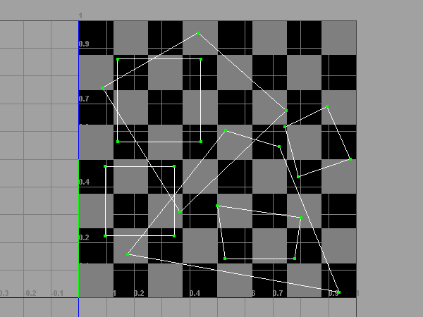
Returning to the UV Texture Editor, you should see the checker texture in the background. There are three buttons at the top of the window that will let you tweak the appearance of this background image. The  button will toggle the image on and off. The
  button will toggle whether the image is darkened or not. The
  button will toggle whether the image is filtered or not. Try out these buttons now.
Selection and manipulation with UVs is similar to the methods you already know for selecting and manipulating vertices. One difference between the two is that vertices can only be edited in the camera view and UVs can only be edited in the UV Texture Editor. Thus while it is not possible to move a vertex in the UV Texture Editor, you can still select them (This also holds for UVs in the camera view). This is sometimes useful to see which faces are affected by a certain part of the UV map. Use the Right-click menu or hotkeys to change between the edit modes. F12 will change to UV mode. Make sure you are in "UV" mode when editing UVs. Try selecting and editing UVs in the UV Texture Editor now.
Editing UVs by hand can be fairly tedious and so there exists a number of quick and dirty methods of laying out UVs called projections. A projection attempts to lay out the UVs of an object based the expected geometry of the object. The different types of projections can be found under the Create UVs menu. A projection will only operate on the current selection, which may be the entire object or some subset of its elements. You will probably find the Create UVs Based On Camera particularly useful. Try out a number of projections now.
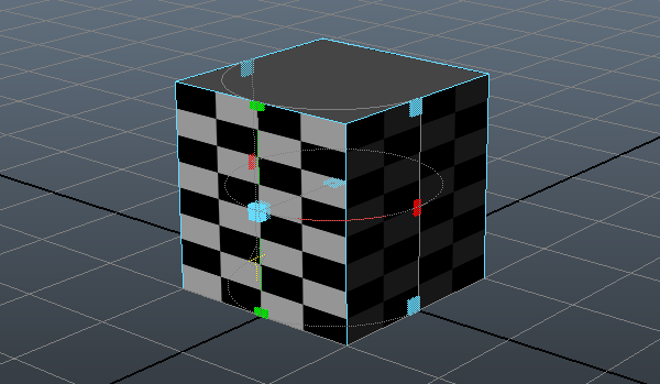
Some projections will present you with a manipulator to tweak the projection after you have applied it. This projection manipulator has two modes, the default of which is Scale and Translate mode. Clicking and dragging on the various handles will allow you to adjust the projection in various ways. Click the "T" in the diamond on the manipulator to change to Rotate mode. Try using a Cylindrical Mapping on the cube and adjusting the projection to see how the UV layout is affected in the UV Texture Editor.
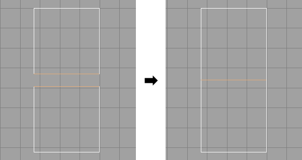
It is frequently the case when creating UV shells that you want a set of UVs to snap to a certain axis. You can do this by selecting the UVs and clicking on of the four Align buttons. The Align buttons are shown as a red arrow pointing a blue line. Try aligning various UVs now.
You may have noticed that when you select an edge in the UV Texture Editor, more than one edge is highlighted. In reality, these two UV edges are the same edge on the model. If you wish to merge these UV edges back into one, hold Shift and Right-click in the UV Texture Editor with the edges selected. From the radial menu, select Sew UVs. Similarly, you can use this menu to cut an existing edge by selecting Cut UVs.
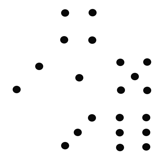
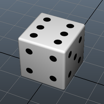
To test out your UV editing skills, apply the dice texture below to a cube. Arrange the UVs such that each face shows the correct number of pips. While it is not particularly important in this example, since the texture shares a common background color, in general you want to keep UV faces from overlapping. You can Bevel the edges of the cube once you are done to make it more realistic.
You now know the basics of UV editing. Continue on to the other exercises to learn more about the basics of Maya.