Modeler Setup
If you unpack the distribution onto your Z: drive, you should only
need to do this once, no matter which machine you use.
- The lab machines already have Tcl/Tk installed, but if you are
working from home, or somewhere that doesn't have Tcl installed, you
can download it from www.scriptics.com. You want
version 8.0.5. Here's the exact download
link.
- Download the project distribution
off the web and unzip it. It has three subdirectories: modeler,
robotarm, and stemthing. It also has the files "modeler.dll",
"modeler.lib", "modeler.tcl", and "modeler.h". I will assume that
I've unzipped the distribution in the "Z:\FOO" directory; you'll have
to change these instructions to correspond to where you unzip it.
- Now you need to set up some environment variables.
You only need to do this once; they should persist when
you log out and log back in. In NT, you go to the System
control panel, and click the Environment tab. In the
Variable: box, type in the name of the variable, and in the
Value: put value you want. Click Set, and then the new variable should be listed
in "User Variables".
Create a variable "TCL" with the path where Tcl was installed (on
the lab machines this is "C:\Program Files\Tcl").
Create a variable "MODELER" with the path where you unpack the
distribution (where the files "modeler.dll" and "modeler.lib" are).
- Now build the projects in the "robotarm" and "stemthing"
subdirectories. Each subdirectory contains an MSVC workspace that you
can open to build the project.
- Now you should be able to start the modeler and load one of the
sample DLLs. To start it, you double-click the "modeler" Tcl script.
Select File > Open model... and load one of
the sample model DLLs (robotarm.dll or stemthing.dll).
Setting up a new model project
Once you can load and view the robot arm and stem thing models
provided in the distribution, you're ready to create your own model.
- In MSVC, select File > New.... Click the Projects
tab and select "Win32 Dynamic-Link Library". Give your project a name
in the Project name: entry box. I'll name my project
"Tralfaz". Click OK, then Finish, then OK to
create an empty DLL project.
- Use your favorite text editor to create the model source file -
mine is called "tralfaz.cpp". Enter the following outline:
#include <modeler.h>

MODEL(Tralfaz);

int Model_SetupCmd( ClientData clientdata, Tcl_Interp* interp,
                    int objc, Tcl_Obj* const objv[] )
{
    return TCL_OK;
}

int Model_ResizeCmd( ClientData clientdata, Tcl_Interp* interp,
                     int objc, Tcl_Obj* const objv[] )
{
    int width, height;

    if ( objc != 3 )
    {
	Tcl_SetResult( interp, "wrong # args: should be \"width height\"",
		       TCL_STATIC );
	return TCL_ERROR;
    }

    if ( Tcl_GetIntFromObj( interp, objv[1], &width ) != TCL_OK )
	return TCL_ERROR;
    if ( Tcl_GetIntFromObj( interp, objv[2], &height ) != TCL_OK )
	return TCL_ERROR;

    glMatrixMode( GL_PROJECTION );
    glLoadIdentity();
    gluPerspective( 30.0, (double)width / height, 1.0, 100.0 );
    glViewport( 0, 0, width, height );

    glClearColor( 0.0, 0.0, 0.0, 0.0 );

    return TCL_OK;
}

int Model_RedrawCmd( ClientData clientdata, Tcl_Interp* interp,
                     int objc, Tcl_Obj* const objv[] )
{
    glClear( GL_COLOR_BUFFER_BIT | GL_DEPTH_BUFFER_BIT );
    draw_mode_setup();

    return TCL_OK;
}
The argument to the MODEL macro on the second line must match the name
of your project. The first letter should be capitalized and the rest
of the letters lowercase. If the case is wrong it won't work!
- Save the file. In MSVC, add the file to the project by selecting
Project > Add To Project > Files....
- Now configure the project. Choose Project > Settings... to
bring up the configuration dialog.
- At the upper left there is a dropdown labeled Settings
For:. Select "All configurations."
- Under the C/C++ tab, select the "Preprocessor" category.
In the "Additional include directories" box, enter:
"$(TCL)\include", "$(MODELER)"
- Under the Link tab, select the "General" category. In the
"Object/library modules:" box, add (don't delete what's already there!) the
following:
"$(TCL)\lib\tcl80.lib" "$(TCL)\lib\tk80.lib" "$(MODELER)\modeler.lib" opengl32.lib glu32.lib
- Click OK.
- Now you can build the project. You'll get a "Debug" subdirectory
with your model DLL in it ("tralfaz.dll" in my example). If you start
the modeler and load the model in, you'll see a black screen.
- This step is optional, but will make your life easier. To easily
run your project, you can configure your project to start the modeler
Tcl script when you debug from within MSVC. Go back into the project
settings dialog (Project > Settings...).
- Select "All Configurations" under Settings For:. Click the
Debug tab.
- In "Executable for debug session:", put the value of your TCL
environment variable, plus the string "\bin\wish80.exe". Note that
you can't use "$(TCL)", you have to type in the path yourself (thank
you, Microsoft). For the lab machines, you'll put in:
c:\program files\tcl\bin\wish80.exe
- In "Program arguments:", put "-f ", plus the value of your MODELER environment
variable, plus "\modeler.tcl". In my example, I'd put in
-f z:\foo\modeler.tcl
The space between the "-f" and the pathname is significant.
- If you give another argument to the modeler, it will assume that
it is a pathname to a model DLL you want loaded when the program
starts. As you're creating your model, you will be running the
modeler over and over to view it. If you want to avoid having to load
it manually every time, change the "Program arguments:" field to
include the full pathname of the model DLL:
-f z:\foo\modeler.tcl z:\foo\robotarm\debug\robotarm.dll
Now when you debug from within MSVC (Build > Start Debug >
Go, or press F5), it will start the modeler for you (and, if you
did step (d), load a model).
Creating a model
A black screen isn't a very interesting model, so let's draw something.
Your model consists of 3 C++ functions. You can largely ignore all
the arguments, they are standard Tcl interface boilerplate. Let's
look at what the three functions do.
Model_SetupCmd gets called once, when your model is first
loaded. This is empty now, we'll see some things to do with this
later.
Model_ResizeCmd gets called when the size of the output window,
to set up the OpenGL camera parameters. It gets passed the new width
and height of the window, which is what all the
Tcl_GetIntFromObj stuff is about. The code above sets up
a plain vanilla perspective projection. You can change this if you
want but shouldn't really need to.
Model_RedrawCmd is where the action is. It gets called every
time the window needs to be redrawn.
First, you need to clear the window, and do some modeler
initialization - this code is provided for you. To draw something,
you call one of primitive object functions provided in the modeler
library:
- sphere( r )
- draws a sphere of radius r.
- box( x, y, z )
- draws a box with corners at (0,0,0) and (x,y,z).
- cylinder( h, r1, r2 )
- draws a cylinder with axis from the origin to (0,0,h). The
radius at the origin is r1; the radius at z=h is
r2. If r1 and r2 are different, you get a
frustum. If r1 or r2 is zero, you get a cone.
- triangle( x1, y1, z1, x2, y2, z2, x3, y3, z3 )
- draws a triangle with vertices at the three given points.
Let's draw a sphere. Add this line to Model_RedrawCmd (between
draw_mode_setup(); and the return):
sphere( 1.0 );
When you load this model, you'll still see nothing. Why? Because the
sphere is centered at the origin, which is exactly where the camera
is. We're inside the sphere, so we don't see anything. Let's move
the sphere so we can see it. The default camera is looking down the
-z axis, so translate the sphere in that direction.
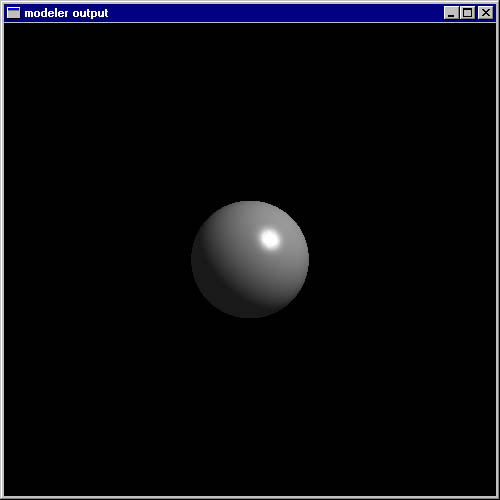
glTranslatef( 0.0, 0.0, -15.0 );
sphere( 1.0 );
Now we get:
Experiment with the other primitives.
We can set material properties with four other functions:
- ambient_color( r, g, b );
- diffuse_color( r, g, b );
- specular_color( r, g, b );
- shininess( s );
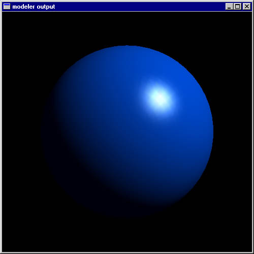
glTranslatef( 0.0, 0.0, -15.0 );
ambient_color( 0.0, 0.0, 0.2 );
diffuse_color( 0.0, 0.3, 0.8 );
sphere( 1.0 );
|
|
Adding interactive controls
Both of the sample models have UI widgets that you can interact with
to change the model. Now we'll see how to add those, allowing the
user to vary the radius of the sphere in our simple example.
Each control widget that you want must have a unique integer ID. To
keep these straight, we recommend using #define'd constants. Stick
#define SPHERE_RADIUS 1
somewhere at the top of your file. Note that this doesn't mean the
radius of the sphere is 1 unit, it means that control #1 is going to
control the radius. We can use any number as the ID, as long as it
is unique in the model.
Model_SetupCmd is where we create the widgets. The available
commands to create widgets are listed below. The first argument to
each one should be the interp argument passed to
Model_SetupCmd; just pass it straight through.
- scale( interp, id, name, min, max, res, start )
- Create a slider widget. res is the resolution of the
slider (the smallest amount you can move it). start is the
initial value. name, as in all these calls, is a string that
labels the widget.
- checkbox( interp, id, name, start )
- Create a checkbox. start is the initial setting.
- radiobutton( interp, id, name, start, ... )
- menu( interp, id, name, start, ... )
- Create a selection widget - either a set of radio buttons or a
menu of choices. The "..." arguments are one or more strings,
terminated with NULL - these are the available choices. They are
numbered choice 0, 1, 2, and so on. start is the initial
selection.
Let's create a slider for the sphere. In Model_SetupCmd, add
this line:
scale( interp, SPHERE_RADIUS, "radius", 0.1, 3.0, 0.01, 1.0 );
Now, in the model drawing function, we need to read the current value
of the slider. Widget settings can be read with the
get_control_* functions, where "*" is one of "d" (to read a
double), "i" (to read an int), or "b" (to read a boolean). You pass
the function the ID of the control whose value you want.
In Model_RedrawCmd, replace
sphere( 1.0 );
with
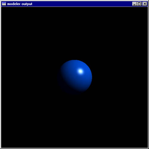
sphere( get_control_d( SPHERE_RADIUS ) );
Now when you load the model, there will be a slider added to the main
window. Moving the slider will change the radius of the sphere:
The sample model "stemthing" has examples of using all available types
of controls.
Animation
The modeler has a simple animation mode, in which it will
automatically redraw the model periodically (instead of just when a
control widget is changed). You can use the function
get_time() to retrieve the current time in seconds since the
start of the animation.
The stemthing model uses this as well. Set the "rotation speed"
slider to something nonzero, then turn on animation mode, and the
model will start to spin.
If your computer can't keep up with the redraw rate in animation mode,
try lowering the quality on the draw menu, so that fewer polygons are
generated.