Quick Links - Modeler Groups
- Skeleton Code for Modeler (zip)
- FLTK (1.1.7) headers and library (zip)
- How to use and extend the modeler
- Sample executables (also check out the winners from previous
quarters linked below)
- Official OpenGL documentation
- Some great OpenGL tutorials
- Help Session Slides
- Help session code
Project Description
In this project you define a 3D model and controls for moving it, and then display and operate the model. The project skeleton contains the framework code for the UI as well as some functions for drawing primitives. You will specify your model in a separate source file that will be compiled and linked in with the existing code.
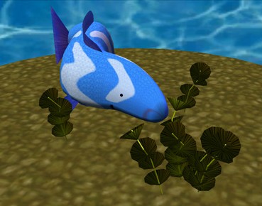
How cool is this project? Some of what you can produce can be found here:
Project Objectives
In this project you will use OpenGL to create and animate a character of your own design. You will become familiar with 3D hierarchical modeling and transformations.
Getting Started
Your project source code is at /projects/instr/06au/cse457 under a folder name corresponding to the group ids that were emailed to you; You will find two source control folders there: source_cvs and source_svn. One is a CVS repository and the second is a Subversion repository. The CVS repository can be used in a similar manner to the previous project. The SVN repository is there for those who prefer that source control system. Before starting on the project, pick only one of those source folders to use/keep and delete the other one to avoid later confusion. Do not delete a repository that contains files you wish to save.
Open modeler.sln to build and run the program from within .NET Developer Studio.
If you plan to work from home, you will need to download and setup Fltk yourselves. For Windows users, this will involve unzipping the file to the location of your choice, and then pointing Visual Studio at the correct include and library directories. To do this in MSVC 6, go to Tools->Options, and select the 'Directories' tab. Fill in the blanks to wherever you located the fltk directory. Note that we are not supporting Linux development, though you are free to try it on your own. More complete setup directions for Win32/Linux can be found here.
WARNING: We strongly discourage editing the modelerapp and modelerdraw classes. For the Animator project, you will be re-using your new model source file and plugging it into a different application. Thus, if your model library depends on changes or additions you make to the modelerapp or modelerdraw classes, it may not be compatible with the Animator skeleton application. You should be able to implement almost all of the bells and whistles inside your new model source file. Some changes can safely be made to the modelerview class for adding extra camera control functionality; the appropriate source files are documented to indicate where your code should be added. What is a Hierarchical Model?
A hierarchical model is a way of grouping together shapes and attributes to form a complex object. Parts of the object are defined in relationship to each other as opposed to their position in some absolute coordinate system. Think of each object as a tree, with nodes decreasing in complexity as you move from root to leaf. Each node can be treated as a single object, so that when you modify a node you end up modifying all its children together. Hierarchical modeling is a very common way to structure 3D scenes and objects, and is found in many other contexts. If hierarchical modeling is unclear to you, you are encouraged to look at the relevant lecture notes. Project Requirements
This project does not have a lot of requirements. However, the additions that we do require are definitely more complex than the ones for the first project. Also, there are many more possibilities to extend your project! Please start early.
Other than these requirements, you have complete artistic freedom on this, so be creative!
Bells and Whistles
One bell is worth two whistles.
![[whistle]](images/whistle.gif) Change the default light source to illuminate your scene more dramatically. It should be controllable by a slider (perhaps by changing its position or color).
Change the default light source to illuminate your scene more dramatically. It should be controllable by a slider (perhaps by changing its position or color). Come up with another whistle and implement it. A whistle is something that extends the use of one of the things you are already doing. It is part of the basic model construction, but extended or cloned and modified in an interesting way. ![[bell]](images/bell.gif) Use a texture map on all or part of your character. (The safest way to do this is to implement your own primitives inside your model file that do texture mapping.) Use a texture map on all or part of your character. (The safest way to do this is to implement your own primitives inside your model file that do texture mapping.) Build a complex shape as a set of polygonal faces, using triangles (either the provided primitive or straight OpenGL triangles) to render it. Examples of things that don't count as complex: a pentagon, a square, a circle. Examples of what does count: dodecahedron, 2D function plot (z = sin(x2 + y)), etc.
Make an additional "animated" sequence your character can perform. Although you can try to use a timed callback, an easier solution is just to increment values each time your model's draw() function is called. If you use the menu option to turn on animation, your draw() function will be executed at around 30 times per second.
Add some widgets that control adjustable parameters to your model so that you can create individual-looking instances of your character. Try to make these actually different individuals, not just "the red guy" and "the blue guy."
Use openGL display lists to speed up the rendering of one or more of your more complicated models. Display lists allow you to render complicated polygons much more quickly by storing more information directly on the graphics card. That way much less informaiton is sent across the (slow) computer bus for each frame rendered. A display list tutorial can be found here.
Implement a smooth curve functionality. Examples of smooth curves are here. These curves are a great way to lead into swept surfaces (see below). Functional curves will need to be demonstrated in some way. One great example would be to draw some polynomial across a curve that you define. Students who implement swept surfaces will not be given a bell for smooth curves. That bell will be included in the swept surfaces bell. Smooth curves will be an important part of the animator project, so this will give you a leg up on that.
![[bell+whistle]](images/bell_whistle.gif) Implement the "Hitchcock Effect" described in class, where the camera zooms in on an object, whilst at the same time pulling away from it (the effect can also be reversed--zoom out and pull in) . The transformation should fix one plane in the scene--show this plane. Make sure that the effect is dramatic--adding an interesting background will help, otherwise it can be really difficult to tell if it's being done correctly. Implement the "Hitchcock Effect" described in class, where the camera zooms in on an object, whilst at the same time pulling away from it (the effect can also be reversed--zoom out and pull in) . The transformation should fix one plane in the scene--show this plane. Make sure that the effect is dramatic--adding an interesting background will help, otherwise it can be really difficult to tell if it's being done correctly.
The camera code has a constrained up vector -- modify the code to (1) handle camera twists (the framework is already there) and (2) ensure that controlling the camera remains intuitive. Note: in the past, we've seen many (incorrect) solutions that simply perform the twist without making the mouse control intuitive. The camera rotation control (left click) should always pivot the camera about an axis that is vertical with respect to the viewer.
Heightfields are great ways to build complicated looking maps and terrains pretty easily.
Add a function in your model file for drawing a new type of primitive. The following examples will definitely garner two bells; if you come up with your own primitive, you will be awarded one or two bells based on its coolness. - Swept surfaces -- given two curves, sweep one profile curve along the path defined by the other. These are also known as "generalized cylinders" when the profile curve is closed. This isn't quite as simple as it may first sound, as it requires the profile curve to change its orientation as it sweeps over the path curve. See this page for some uses of generalized cylinders. This document may be helpful as well. Also, ask Steve if you're really stuck.
- Surfaces of rotation - given a curve and an axis, draw the surface that results from sweeping the curve around the axis. This is really nice for making pottery :).
- Rail surfaces - see Watt, p. 41.
(Variable) Use some sort of procedural modeling (such as an L-system) to generate all or part of your character. Have parameters of the procedural modeler controllable by the user via control widgets. Last quarter, one group generated these awesome results.
In addition to mood cycling, have your character react differently to UI controls depending on what mood they are in. Again, there is some weight in this item because the character reactions are supposed to make sense in a story telling way. Think about the mood that the character is in, think about the things that you might want the character to do, and then provide a means for expressing and controlling those actions.
One difficulty with hierarchical modeling using primitives is the difficulty of building "organic" shapes. It's difficult, for instance, to make a convincing looking human arm because you can't really show the bending of the skin and bulging of the muscle using cylinders and spheres. There has, however, been success in building organic shapes using
metaballs. Implement your hierarchical model and "skin" it with metaballs. Hint: look up "marching cubes" and "marching tetrahedra" --these are two commonly used algorithms for volume rendering. For an additional bell, the placement of the metaballs should depend on some sort of interactically controllable hierarchy. Try out a demo application. Metaball Demos: These demos show the use of metaballs within the modeler framework. The first demo allows you to play around with three metaballs just to see how they interact with one another. The second demo shows an application of metaballs to create a twisting snake-like tube. Both these demos were created using the metaball implementation from a past CSE 457 student's project. Demo 1: Basic Texture Mapped Metaballs Demo 2: Cool Metaball Snake If you have a sufficiently complex model, you'll soon realize what a pain it is to have to play with all the sliders to pose your character correctly. Implement a method of adjusting the joint angles, etc., directly though the viewport. For instance, clicking on the shoulder of a human model might select it and activate a sphere around the joint. Click-dragging the sphere then should rotate the shoulder joint intuitively. For the elbow joint, however, a sphere would be quite unintuitive, as the elbow can only rotate about one axis. For ideas, you may want to play with the Maya 3D modeling/animation package, which is installed on the workstations in 228. Credit depends on quality of implementation. Another method to build organic shapes is subdivision surfaces. Implement these for use in your model. You may want to visit this to get some starter code.
Disclaimer: please consult the course staff before spending any serious time on these. They are quite difficult, and credit can vary depending on the quality of your method and implementation.  Inverse kinematics
The hierarchical model that you created is controlled by forward kinematics; that is, the positions of the parts vary as a function of joint angles. More mathematically stated, the positions of the joints are computed as a function of the degrees of freedom (these DOFs are most often rotations). The problem of inverse kinematics is to determine the DOFs of a model to satisfy a set of positional constraints, subject to the DOF constraints of the model (a knee on a human model, for instance, should not bend backwards). This is a significantly harder problem than forward kinematics. Aside from the complicated math involved, many inverse kinematics problems do not have unique solutions. Imagine a human model, with the feet constrained to the ground. Now we wish to place the hand, say, about five feet off the ground. We need to figure out the value of every joint angle in the body to achieve the desired pose. Clearly, there are an infinite number of solutions. Which one is "best"?
Now imagine that we wish to place the hand 15 feet off the ground. It's fairly unlikely that a realistic human model can do this with its feet still planted on the ground. But inverse kinematics must provide a good solution anyway. How is a good solution defined? Your solver should be fully general and not rely on your specific model (although you can assume that the degrees of freedom are all rotational). Additionally, you should modify your user interface to allow interactive control of your model though the inverse kinematics solver. The solver should run quickly enough to respond to mouse movement. If you're interested in implementing this, you will probably want to consult the CSE558 lecture notes. View-dependent adaptive polygon meshes The primitives that you are using in your model are all built from simple two dimensional polygons. That's how most everything is handled in the OpenGL graphics world. Everything ends up getting reduced to triangles. Building a highly detailed polygonal model often requires millions of triangles. This can be a huge burden on the graphics hardware. One approach to alleviating this problem is to draw the model using varying levels of detail. In the modeler application, this can be done by specifying the quality (poor, low, medium, high). This unfortunately is a fairly hacky solution to a more general problem. First, implement a method for controlling the level of detail of an arbitrary polygonal model. You will probably want to devise some way of representing the model in a file. Ideally, you should not need to load the entire file into memory if you're drawing a low-detail representation. Now the question arises: how much detail do we need to make a visually nice image? This depends on a lot of factors. Farther objects can be drawn with fewer polygons, since they're smaller on screen. See Hugues Hoppe's work on View-dependent refinement of progressive meshes for some cool demos of this. Implement this or a similar method, making sure that your user interface supplies enough information to demonstrates the benefit of using your method. There are many other criteria to consider that you may want to use, such as lighting and shading (dark objects require less detail than light ones; objects with matte finishes require less detail than shiny objects). Hierarchical models from polygon meshes Many 3D models come in the form of static polygon meshes. That is, all the geometry is there, but there is no inherent hierarchy. These models may come from various sources, for instance 3D scans. Implement a system to easily give the model some sort of hierarchical structure. This may be through the user interface, or perhaps by fitting an model with a known hierarchical structure to the polygon mesh (see this for one way you might do this). If you choose to have a manual user interface, it should be very intuitive. Through your implementation, you should be able to specify how the deformations at the joints should be done. On a model of a human, for instance, a bending elbow should result in the appropriate deformation of the mesh around the elbow (and, if you're really ambitious, some bulging in the biceps). |