Lab 6: network and web server
Due: Mon, 12 Dec 2016 23:00:00 -0800
This is one of your lab X options.
Introduction
Now that you have a file system, no self respecting OS should go without a network stack. In this the lab you are going to write a driver for a network interface card. The card will be based on the Intel 82540EM chip, also known as the E1000.
Getting started
Use Git to fetch the latest version of the course repository, and
then create a local branch called lab6 based on our branch,
origin/lab6:
$ cd lab
$ add git
$ git commit -am 'my solution to lab5'
nothing to commit (working directory clean)
$ git pull
Already up-to-date.
$ git checkout -b lab6 origin/lab6
Branch lab6 set up to track remote branch refs/remotes/origin/lab6.
Switched to a new branch "lab6"
$ git merge lab5
Merge made by recursive.
 fs/fs.c |   42 +++++++++++++++++++
 1 files changed, 42 insertions(+), 0 deletions(-)
$
The network card driver, however, will not be enough to get your
OS hooked up to the Internet. In the new lab 6 code, we have provided
you with a network stack and a network server. As in previous labs,
use git to grab the code for this lab, merge in your own code, and
explore the contents of the new net/ directory, as well as the new
files in kern/.
In addition to writing the driver, you will need to create a system call interface to give access to your driver. You will implement missing network server code to transfer packets between the network stack and your driver. You will also tie everything together by finishing a web server. With the new web server you will be able to serve files from your file system.
Much of the kernel device driver code you will have to write yourself from scratch. This lab provides much less guidance than previous labs: there are no skeleton files, no system call interfaces written in stone, and many design decisions are left up to you. For this reason, we recommend that you read the entire assignment write up before starting any individual exercises. Many students find this lab more difficult than previous labs, so please plan your time accordingly.
As before, you will need to do all of the regular exercises described
in the lab. Write up brief answers to the questions posed in the
lab in answers-lab6.txt.
QEMU’s virtual network
We will be using QEMU’s user mode network stack since it requires no administrative privileges to run. QEMU’s documentation has more about user-net here. We’ve updated the makefile to enable QEMU’s user-mode network stack and the virtual E1000 network card.
By default, QEMU provides a virtual router running on IP 10.0.2.2
and will assign JOS the IP address 10.0.2.15. To keep things simple,
we hard-code these defaults into the network server in net/ns.h.
While QEMU’s virtual network allows JOS to make arbitrary connections out to the Internet, JOS’s 10.0.2.15 address has no meaning outside the virtual network running inside QEMU (that is, QEMU acts as a NAT), so we can’t connect directly to servers running inside JOS, even from the host running QEMU. To address this, we configure QEMU to run a server on some port on the host machine that simply connects through to some port in JOS and shuttles data back and forth between your real host and the virtual network.
You will run JOS servers on ports 7 (echo) and 80 (http). To avoid
collisions on shared attu machines, the makefile generates
forwarding ports for these based on your user ID. To find out what
ports QEMU is forwarding to on your development host, run make which-ports.
For convenience, the makefile also provides make nc-7
and make nc-80, which allow you to interact directly with servers
running on these ports in your terminal. (These targets only connect
to a running QEMU instance; you must start QEMU itself separately.)
Packet inspection
The makefile also configures QEMU’s network stack to record all
incoming and outgoing packets to qemu.pcap in your lab directory.
To get a hex/ASCII dump of captured packets use tcpdump like this:
$ tcpdump -XXnr qemu.pcapAlternatively, you can use Wireshark to graphically inspect the pcap file. Wireshark also knows how to decode and inspect hundreds of network protocols.
Debugging the E1000
We are very lucky to be using emulated hardware. Since the E1000 is running in software, the emulated E1000 can report to us, in a user readable format, its internal state and any problems it encounters. Normally, such a luxury would not be available to a driver developer writing with bare metal.
The E1000 can produce a lot of debug output, so you have to enable specific logging channels. Some channels you might find useful are:
| Flag | Meaning |
|---|---|
| tx | Log packet transmit operations |
| txerr | Log transmit ring errors |
| rx | Log changes to RCTL |
| rxfilter | Log filtering of incoming packets |
| rxerr | Log receive ring errors |
| unknown | Log reads and writes of unknown registers |
| eeprom | Log reads from the EEPROM |
| interrupt | Log interrupts and changes to interrupt registers |
To enable “tx” and “txerr” logging, for example, use make E1000_DEBUG=tx,txerr ....
E1000_DEBUG
Note: E1000_DEBUG flags only work in the course version of QEMU.
You can take debugging using software emulated hardware one step
further. If you are ever stuck and do not understand why the E1000
is not responding the way you would expect, you can look at QEMU’s
E1000 implementation in hw/e1000.c.
The network server
Writing a network stack from scratch is hard work. Instead, we will be using lwIP, an open source lightweight TCP/IP protocol suite that among many things includes a network stack. In this assignment, as far as we are concerned, lwIP is a black box that implements a BSD socket interface and has a packet input port and packet output port.
The network server is actually a combination of four environments:
- core network server environment (includes socket call dispatcher and lwIP)
- input environment
- output environment
- timer environment
The following diagram shows the different environments and their relationships. The diagram shows the entire system including the device driver, which will be covered later. In this lab, you will implement the parts highlighted in green.

The core network server environment
The core network server environment is composed of the socket call
dispatcher and lwIP itself. The socket call dispatcher works exactly
like the file server. User environments use stubs (found in
lib/nsipc.c) to send IPC messages to the core network environment.
If you look at lib/nsipc.c you will see that we find the core network
server the same way we found the file server: i386_init created the
NS environment with NS_TYPE_NS, so we scan envs, looking for this
special environment type. For each user environment IPC, the
dispatcher in the network server calls the appropriate BSD socket
interface function provided by lwIP on behalf of the user.
Regular user environments do not use the nsipc_* calls directly.
Instead, they use the functions in lib/sockets.c, which provides a
file descriptor-based sockets API. Thus, user environments refer
to sockets via file descriptors, just like how they referred to
on-disk files. A number of operations (connect, accept, etc.) are
specific to sockets, but read, write, and close go through the
normal file descriptor device-dispatch code in lib/fd.c. Much like
how the file server maintained internal unique ID’s for all open
files, lwIP also generates unique ID’s for all open sockets. In
both the file server and the network server, we use information
stored in struct Fd to map per-environment file descriptors to these
unique ID spaces.
Even though it may seem that the IPC dispatchers of the file server and network server act the same, there is a key difference. BSD socket calls like accept and recv can block indefinitely. If the dispatcher were to let lwIP execute one of these blocking calls, the dispatcher would also block and there could only be one outstanding network call at a time for the whole system. Since this is unacceptable, the network server uses user-level threading to avoid blocking the entire server environment. For every incoming IPC message, the dispatcher creates a thread and processes the request in the newly created thread. If the thread blocks, then only that thread is put to sleep while other threads continue to run.
In addition to the core network environment there are three helper environments. Besides accepting messages from user applications, the core network environment’s dispatcher also accepts messages from the input and timer environments.
The output environment
When servicing user environment socket calls, lwIP will generate
packets for the network card to transmit. LwIP will send each packet
to be transmitted to the output helper environment using the
NSREQ_OUTPUT IPC message with the packet attached in the page
argument of the IPC message. The output environment is responsible
for accepting these messages and forwarding the packet on to the
device driver via the system call interface that you will soon
create.
The input environment
Packets received by the network card need to be injected into lwIP.
For every packet received by the device driver, the input environment
pulls the packet out of kernel space (using kernel system calls
that you will implement) and sends the packet to the core server
environment using the NSREQ_INPUT IPC message.
The packet input functionality is separated from the core network
environment because JOS makes it hard to simultaneously accept IPC
messages and poll or wait for a packet from the device driver. We
do not have a select system call in JOS that would allow environments
to monitor multiple input sources to identify which input is ready
to be processed.
If you take a look at net/input.c and net/output.c you will see
that both need to be implemented. This is mainly because the
implementation depends on your system call interface. You will write
the code for the two helper environments after you implement the
driver and system call interface.
The timer environment
The timer environment periodically sends messages of type NSREQ_TIMER
to the core network server notifying it that a timer has expired.
The timer messages from this thread are used by lwIP to implement
various network timeouts.
Initialization and transmitting packets
The network interface card
Writing a driver requires knowing in depth the hardware and the interface presented to the software. The lab text will provide a high-level overview of how to interface with the E1000, but you’ll need to make extensive use of Intel’s manual while writing your driver.
Discovery
Exercise
Browse Intel’s Software Developer’s Manual for the E1000. This manual covers several closely related Ethernet controllers. QEMU emulates the 82540EM.
You should skim over chapter 2 now to get a feel for the device. To write your driver, you’ll need to be familiar with chapters 3 and 14, as well as 4.1 (though not 4.1’s subsections). You’ll also need to use chapter 13 as reference. The other chapters mostly cover components of the E1000 that your driver won’t have to interact with. Don’t worry about the details right now; just get a feel for how the document is structured so you can find things later.
While reading the manual, keep in mind that the E1000 is a sophisticated device with many advanced features. A working E1000 driver only needs a fraction of the features and interfaces that the NIC provides. Think carefully about the easiest way to interface with the card. We strongly recommend that you get a basic driver working before taking advantage of the advanced features.
Like the NVMe disk, the E1000 is also a PCI device.
Similarly, you’ll need to help JOS discover the E1000 device.
You may find the nvm_attach function in kern/nvme.c useful.
Exercise
Implement an attach function to initialize the E1000. Add an entry
to the pci_attach_vendor array in kern/pci.c to trigger your function
if a matching PCI device is found (be sure to put it before the {0,
0, 0} entry that mark the end of the table). You can find the vendor
ID and device ID of the 82540EM that QEMU emulates in section 5.2.
You should also see these listed when JOS scans the PCI bus while
booting.
For now, just enable the E1000 device via pci_func_enable. We’ll
add more initialization throughout the lab.
We have provided the kern/e1000.c and kern/e1000.h files for you
so that you do not need to mess with the build system. They are
currently blank; you need to fill them in for this exercise. You
may also need to include the kern/e1000.h file in other places in the
kernel.
When you boot your kernel, you should see it print that the PCI
function of the E1000 card was enabled. Your code should now pass
the pci attach test.
Now you need to negotiates an MMIO region with the E1000 and stores
its base and size in BAR 0 (that is, reg_base[0] and reg_size[0]).
Exercise
In your attach function, create a virtual memory mapping for the
E1000’s BAR 0 by calling mmio_map_region.
You’ll want to record the location of this mapping in a variable so you can later access the registers you just mapped. If you do use a pointer to the device register mapping, be sure to declare it volatile; otherwise, the compiler is allowed to cache values and reorder accesses to this memory.
To test your mapping, try printing out the device status register
(section 13.4.2). This is a 4 byte register that starts at byte 8
of the register space. You should get 0x80080783, which indicates
a full duplex link is up at 1000 MB/s, among other things.
Hint: You’ll need a lot of constants, like the locations of registers and values of bit masks. Trying to copy these out of the developer’s manual is error-prone and mistakes can lead to painful debugging sessions. We recommend instead using QEMU’s e1000_hw.h header as a guideline. We don’t recommend copying it in verbatim, because it defines far more than you actually need and may not define things in the way you need, but it’s a good starting point.
DMA
You could imagine transmitting and receiving packets by writing and reading from the E1000’s registers, but this would be slow and would require the E1000 to buffer packet data internally. Instead, the E1000 uses Direct Memory Access (DMA) to read and write packet data directly from memory without involving the CPU. The driver is responsible for allocating memory for the transmit and receive queues, setting up DMA descriptors, and configuring the E1000 with the location of these queues, but everything after that is asynchronous. To transmit a packet, the driver copies it into the next DMA descriptor in the transmit queue and informs the E1000 that another packet is available; the E1000 will copy the data out of the descriptor when there is time to send the packet. Likewise, when the E1000 receives a packet, it copies it into the next DMA descriptor in the receive queue, which the driver can read from at its next opportunity.
The receive and transmit queues are very similar at a high level. Both consist of a sequence of descriptors. While the exact structure of these descriptors varies, each descriptor contains some flags and the physical address of a buffer containing packet data (either packet data for the card to send, or a buffer allocated by the OS for the card to write a received packet to).
The queues are implemented as circular arrays, meaning that when the card or the driver reach the end of the array, it wraps back around to the beginning. Both have a head pointer and a tail pointer and the contents of the queue are the descriptors between these two pointers. The hardware always consumes descriptors from the head and moves the head pointer, while the driver always add descriptors to the tail and moves the tail pointer. The descriptors in the transmit queue represent packets waiting to be sent (hence, in the steady state, the transmit queue is empty). For the receive queue, the descriptors in the queue are free descriptors that the card can receive packets into (hence, in the steady state, the receive queue consists of all available receive descriptors).
The pointers to these arrays as well as the addresses of the packet buffers in the descriptors must all be physical addresses because hardware performs DMA directly to and from physical RAM without going through the MMU.
Transmitting packets
The transmit and receive functions of the E1000 are basically independent of each other, so we can work on one at a time. We’ll attack transmitting packets first simply because we can’t test receive without transmitting an “I’m here!” packet first.
First, you’ll have to initialize the card to transmit, following the steps described in section 14.5 (you don’t have to worry about the subsections). The first step of transmit initialization is setting up the transmit queue. The precise structure of the queue is described in section 3.4 and the structure of the descriptors is described in section 3.3.3. We won’t be using the TCP offload features of the E1000, so you can focus on the “legacy transmit descriptor format.” You should read those sections now and familiarize yourself with these structures.
C structures
You’ll find it convenient to use C structs to describe the E1000’s
structures. As you’ve seen with structures like the struct Trapframe,
C structs let you precisely layout data in memory. C can insert
padding between fields, but the E1000’s structures are laid out
such that this shouldn’t be a problem. If you do encounter field
alignment problems, look into GCC’s packed attribute.
As an example, consider the legacy transmit descriptor given in table 3-8 of the manual and reproduced here:
63            48 47   40 39   32 31   24 23   16 15             0
+---------------------------------------------------------------+
|                         Buffer address                        |
+---------------+-------+-------+-------+-------+---------------+
|    Special    |  CSS  | Status|  Cmd  |  CSO  |    Length     |
+---------------+-------+-------+-------+-------+---------------+
The first byte of the structure starts at the top right, so to convert this into a C struct, read from right to left, top to bottom. If you squint at it right, you’ll see that all of the fields even fit nicely into a standard-size types:
struct tx_desc {
	uint64_t addr;
	uint16_t length;
	uint8_t cso;
	uint8_t cmd;
	uint8_t status;
	uint8_t css;
	uint16_t special;
} __attribute__((packed));
Your driver will have to reserve memory for the transmit descriptor array and the packet buffers pointed to by the transmit descriptors. There are several ways to do this, ranging from dynamically allocating pages to simply declaring them in global variables. Whatever you choose, keep in mind that the E1000 accesses physical memory directly, which means any buffer it accesses must be contiguous in physical memory.
There are also multiple ways to handle the packet buffers. The simplest, which we recommend starting with, is to reserve space for a packet buffer for each descriptor during driver initialization and simply copy packet data into and out of these pre-allocated buffers. The maximum size of an Ethernet packet is 1518 bytes, which bounds how big these buffers need to be. More sophisticated drivers could dynamically allocate packet buffers (e.g., to reduce memory overhead when network usage is low) or even pass buffers directly provided by user space (a technique known as “zero copy”), but it’s good to start simple.
Exercise
Perform the initialization steps described in section 14.5 (but not its subsections). Use section 13 as a reference for the registers the initialization process refers to and sections 3.3.3 and 3.4 for reference to the transmit descriptors and transmit descriptor array.
Be mindful of the alignment requirements on the transmit descriptor array and the restrictions on length of this array. Since TDLEN must be 128-byte aligned and each transmit descriptor is 16 bytes, your transmit descriptor array will need some multiple of 8 transmit descriptors. However, don’t use more than 64 descriptors or our tests won’t be able to test transmit ring overflow.
For the TCTL.COLD, you can assume full-duplex operation. For TIPG, refer to the default values described in table 13-77 of section 13.4.34 for the IEEE 802.3 standard IPG (don’t use the values in the table in section 14.5).
Try running make E1000_DEBUG=TXERR,TX qemu. If you are using the course qemu, you should see an “e1000: tx disabled” message when you set the TDT register (since this happens before you set TCTL.EN) and no further “e1000” messages.
Now that transmit is initialized, you’ll have to write the code to transmit a packet and make it accessible to user space via a system call. To transmit a packet, you have to add it to the tail of the transmit queue, which means copying the packet data into the next packet buffer and then updating the TDT (transmit descriptor tail) register to inform the card that there’s another packet in the transmit queue. Note that TDT is an index into the transmit descriptor array, not a byte offset; the documentation isn’t very clear about this.
However, the transmit queue is only so big. What happens if the card has fallen behind transmitting packets and the transmit queue is full? In order to detect this condition, you’ll need some feedback from the E1000. Unfortunately, you can’t just use the TDH (transmit descriptor head) register; the documentation explicitly states that reading this register from software is unreliable. However, if you set the RS bit in the command field of a transmit descriptor, then, when the card has transmitted the packet in that descriptor, the card will set the DD bit in the status field of the descriptor. If a descriptor’s DD bit is set, you know it’s safe to recycle that descriptor and use it to transmit another packet.
What if the user calls your transmit system call, but the DD bit
of the next descriptor isn’t set, indicating that the transmit queue
is full? You’ll have to decide what to do in this situation. You
could simply drop the packet. Network protocols are resilient to
this, but if you drop a large burst of packets, the protocol may
not recover. You could tell the user environment that it has to
retry, much like you did for sys_ipc_try_send. This has the advantage
of pushing back on the environment generating the data. You could
spin in the driver until a transmit descriptor frees up, but this
may introduce serious performance problems since the JOS kernel
isn’t designed to block. Finally, you could put the transmitting
environment to sleep and request that the card send an interrupt
when transmit descriptors free up. We recommend that you start with
whatever you think is simplest.
Exercise
Write a function to transmit a packet by checking that the next descriptor is free, copying the packet data into the next descriptor, and updating TDT. Make sure you handle the transmit queue being full.
Now would be a good time to test your packet transmit code. Try transmitting just a few packets by directly calling your transmit function from the kernel. You don’t have to create packets that conform to any particular network protocol in order to test this. Run make E1000_DEBUG=TXERR,TX qemu to run your test. You should see something like:
e1000: index 0: 0x271f00 : 9000002a 0
...
as you transmit packets. Each line gives the index in the transmit array, the buffer address of that transmit descriptor, the cmd/CSO/length fields, and the special/CSS/status fields. If QEMU doesn’t print the values you expected from your transmit descriptor, check that you’re filling in the right descriptor and that you configured TDBAL and TDBAH correctly. If you get “e1000: TDH wraparound @0, TDT x, TDLEN y” messages, that means the E1000 ran all the way through the transmit queue without stopping (if QEMU didn’t check this, it would enter an infinite loop), which probably means you aren’t manipulating TDT correctly. If you get lots of “e1000: tx disabled” messages, then you didn’t set the transmit control register right.
Once QEMU runs, you can then run tcpdump -XXnr qemu.pcap to see the packet data that you transmitted. If you saw the expected “e1000: index” messages from QEMU, but your packet capture is empty, double check that you filled in every necessary field and bit in your transmit descriptors (the E1000 probably went through your transmit descriptors, but didn’t think it had to send anything).
Exercise
Add a system call that lets you transmit packets from user space. The exact interface is up to you. Don’t forget to check any pointers passed to the kernel from user space.
Transmitting packets: network server
Now that you have a system call interface to the transmit side of
your device driver, it’s time to send packets. The output helper
environment’s goal is to do the following in a loop: accept
NSREQ_OUTPUT IPC messages from the core network server and send the
packets accompanying these IPC message to the network device driver
using the system call you added above. The NSREQ_OUTPUT IPC’s are
sent by the low_level_output function in net/lwip/jos/jif/jif.c,
which glues the lwIP stack to JOS’s network system. Each IPC will
include a page consisting of a union Nsipc with the packet in its
struct jif_pkt pkt field (see inc/ns.h). struct jif_pkt looks like:
struct jif_pkt {
	int jp_len;
	char jp_data[0];
};
jp_len represents the length of the packet. All subsequent bytes
on the IPC page are dedicated to the packet contents. Using a
zero-length array like jp_data at the end of a struct is a common
C trick (some would say abomination) for representing buffers without
pre-determined lengths. Since C doesn’t do array bounds checking,
as long as you ensure there’s enough unused memory following the
struct, you can use jp_data as if it were an array of any size.
Be aware of the interaction between the device driver, the output environment and the core network server when there is no more space in the device driver’s transmit queue. The core network server sends packets to the output environment using IPC. If the output environment is suspended due to a send packet system call because the driver has no more buffer space for new packets, the core network server will block waiting for the output server to accept the IPC call.
Exercise
Implement net/output.c.
You can use net/testoutput.c to test your output code without
involving the whole network server, as follows.
First, try running make E1000_DEBUG=TXERR,TX run-net_testoutput.
You should see something like:
Transmitting packet 0
e1000: index 0: 0x271f00 : 9000009 0
Transmitting packet 1
e1000: index 1: 0x2724ee : 9000009 0
...
Then, tcpdump -XXnr qemu.pcap should output
reading from file qemu.pcap, link-type EN10MB (Ethernet)
-5:00:00.600186 [|ether]
	0x0000:  5061 636b 6574 2030 30                   Packet.00
-5:00:00.610080 [|ether]
	0x0000:  5061 636b 6574 2030 31                   Packet.01
...
Try make E1000_DEBUG=TXERR,TX NET_CFLAGS=-DTESTOUTPUT_COUNT=100 run-net_testoutput to test with a larger packet count. If this overflows your transmit ring, double check that you’re handling the DD status bit correctly and that you’ve told the hardware to set the DD status bit (using the RS command bit).
Your code should pass the testoutput tests.
Question
How did you structure your transmit implementation? In particular, what do you do if the transmit ring is full?
Receiving packets and the web server
Receiving packets
Just like you did for transmitting packets, you’ll have to configure the E1000 to receive packets and provide a receive descriptor queue and receive descriptors. Section 3.2 describes how packet reception works, including the receive queue structure and receive descriptors, and the initialization process is detailed in section 14.4.
Exercise
Read section 3.2. You can ignore anything about interrupts and checksum offloading (you can return to these sections if you decide to use these features later), and you don’t have to be concerned with the details of thresholds and how the card’s internal caches work.
When the E1000 receives a packet, it first checks if it matches the card’s configured filters (for example, to see if the packet is addressed to this E1000’s MAC address) and ignores the packet if it doesn’t match any filters. Otherwise, the E1000 tries to retrieve the next receive descriptor from the head of the receive queue. If the head (RDH) has caught up with the tail (RDT), then the receive queue is out of free descriptors, so the card drops the packet. If there is a free receive descriptor, it copies the packet data into the buffer pointed to by the descriptor, sets the descriptor’s DD (Descriptor Done) and EOP (End of Packet) status bits, and increments the RDH.
If the E1000 receives a packet that is larger than the packet buffer in one receive descriptor, it will retrieve as many descriptors as necessary from the receive queue to store the entire contents of the packet. To indicate that this has happened, it will set the DD status bit on all of these descriptors, but only set the EOP status bit on the last of these descriptors. You can either deal with this possibility in your driver, or simply configure the card to not accept “long packets” (also known as jumbo frames) and make sure your receive buffers are large enough to store the largest possible standard Ethernet packet (1518 bytes).
Exercise
Set up the receive queue and configure the E1000 by following the process in section 14.4. You don’t have to support “long packets” or multicast. For now, don’t configure the card to use interrupts; you can change that later if you decide to use receive interrupts. Also, configure the E1000 to strip the Ethernet CRC, since the grade script expects it to be stripped.
By default, the card will filter out all packets. You have to configure the Receive Address Registers (RAL and RAH) with the card’s own MAC address in order to accept packets addressed to that card. You can simply hard-code QEMU’s default MAC address of 52:54:00:12:34:56 (we already hard-code this in lwIP, so doing it here too doesn’t make things any worse). Be very careful with the byte order; MAC addresses are written from lowest-order byte to highest-order byte, so 52:54:00:12 are the low-order 32 bits of the MAC address and 34:56 are the high-order 16 bits.
The E1000 only supports a specific set of receive buffer sizes (given in the description of RCTL.BSIZE in 13.4.22). If you make your receive packet buffers large enough and disable long packets, you won’t have to worry about packets spanning multiple receive buffers. Also, remember that, just like for transmit, the receive queue and the packet buffers must be contiguous in physical memory.
You should use at least 128 receive descriptors.
You can do a basic test of receive functionality now, even without
writing the code to receive packets. Run make
E1000_DEBUG=TX,TXERR,RX,RXERR,RXFILTER run-net_testinput.
testinput will transmit an ARP (Address Resolution Protocol)
announcement packet (using your packet transmitting system call),
which QEMU will automatically reply to. Even though your driver
can’t receive this reply yet, you should see a “e1000: unicast
match[0]: 52:54:00:12:34:56” message, indicating that a packet was
received by the E1000 and matched the configured receive filter.
If you see a “e1000: unicast mismatch: 52:54:00:12:34:56” message
instead, the E1000 filtered out the packet, which means you probably
didn’t configure RAL and RAH correctly. Make sure you got the byte
ordering right and didn’t forget to set the “Address Valid” bit in
RAH. If you don’t get any “e1000” messages, you probably didn’t
enable receive correctly.
Now you’re ready to implement receiving packets. To receive a packet, your driver will have to keep track of which descriptor it expects to hold the next received packet (hint: depending on your design, there’s probably already a register in the E1000 keeping track of this). Similar to transmit, the documentation states that the RDH register cannot be reliably read from software, so in order to determine if a packet has been delivered to this descriptor’s packet buffer, you’ll have to read the DD status bit in the descriptor. If the DD bit is set, you can copy the packet data out of that descriptor’s packet buffer and then tell the card that the descriptor is free by updating the queue’s tail index, RDT.
If the DD bit isn’t set, then no packet has been received. This is the receive-side equivalent of when the transmit queue was full, and there are several things you can do in this situation. You can simply return a “try again” error and require the caller to retry. While this approach works well for full transmit queues because that’s a transient condition, it is less justifiable for empty receive queues because the receive queue may remain empty for long stretches of time. A second approach is to suspend the calling environment until there are packets in the receive queue to process. This tactic is very similar to sys_ipc_recv. Just like in the IPC case, since we have only one kernel stack per CPU, as soon as we leave the kernel the state on the stack will be lost. We need to set a flag indicating that an environment has been suspended by receive queue underflow and record the system call arguments. The drawback of this approach is complexity: the E1000 must be instructed to generate receive interrupts and the driver must handle them in order to resume the environment blocked waiting for a packet.
Exercise
Write a function to receive a packet from the E1000 and expose it to user space by adding a system call. Make sure you handle the receive queue being empty.
If you decide to use interrupts to detect when packets are received,
you’ll need to write code to handle these interrupts. If you do use
interrupts, note that, once an interrupt is asserted, it will remain
asserted until the driver clears the interrupt. In your interrupt
handler make sure to clear the interrupt handled as soon as you
handle it. If you don’t, after returning from your interrupt handler,
the CPU will jump back into it again. In addition to clearing the
interrupts on the E1000 card, interrupts also need to be cleared
on the LAPIC. Use lapic_eoi to do so.
Receiving packets: network server
In the network server input environment, you will need to use your
new receive system call to receive packets and pass them to the
core network server environment using the NSREQ_INPUT IPC message.
These IPC input message should have a page attached with a
union Nsipc with its struct jif_pkt pkt field filled in with the packet
received from the network.
Exercise
Implement net/input.c.
Run testinput again with
make E1000_DEBUG=TX,TXERR,RX,RXERR,RXFILTER run-net_testinput.
You should see:
Sending ARP announcement...
Waiting for packets...
e1000: index 0: 0x26dea0 : 900002a 0
e1000: unicast match[0]: 52:54:00:12:34:56
input: 0000   5254 0012 3456 5255  0a00 0202 0806 0001
input: 0010   0800 0604 0002 5255  0a00 0202 0a00 0202
input: 0020   5254 0012 3456 0a00  020f 0000 0000 0000
input: 0030   0000 0000 0000 0000  0000 0000 0000 0000
The lines beginning with “input:” are a hexdump of QEMU’s ARP reply.
Your code should pass the testinput tests. Note that there’s no
way to test packet receiving without sending at least one ARP packet
to inform QEMU of JOS’ IP address, so bugs in your transmitting
code can cause this test to fail.
To more thoroughly test your networking code, we have provided a
daemon called echosrv that sets up an echo server running on port
7 that will echo back anything sent over a TCP connection. Use
make E1000_DEBUG=TX,TXERR,RX,RXERR,RXFILTER run-echosrv
to start the echo server in one terminal and make nc-7
in another to connect to it. Every line you type should be echoed
back by the server. Every time the emulated E1000 receives a packet,
QEMU should print something like the following to the console:
e1000: unicast match[0]: 52:54:00:12:34:56
e1000: index 2: 0x26ea7c : 9000036 0
e1000: index 3: 0x26f06a : 9000039 0
e1000: unicast match[0]: 52:54:00:12:34:56
At this point, you should also be able to pass the echosrv test.
Question
How did you structure your receive implementation? In particular, what do you do if the receive queue is empty and a user environment requests the next incoming packet?
Challenge: EEPROM
Read about the EEPROM in the developer’s manual and write the code to load the E1000’s MAC address out of the EEPROM. Currently, QEMU’s default MAC address is hard-coded into both your receive initialization and lwIP. Fix your initialization to use the MAC address you read from the EEPROM, add a system call to pass the MAC address to lwIP, and modify lwIP to the MAC address read from the card. Test your change by configuring QEMU to use a different MAC address.
Challenge: zero copy
Modify your E1000 driver to be “zero copy.” Currently, packet data has to be copied from user-space buffers to transmit packet buffers and from receive packet buffers back to user-space buffers. A zero copy driver avoids this by having user space and the E1000 share packet buffer memory directly. There are many different approaches to this, including mapping the kernel-allocated structures into user space or passing user-provided buffers directly to the E1000. Regardless of your approach, be careful how you reuse buffers so that you don’t introduce races between user-space code and the E1000.
Challenge: more zero copy
Take the zero copy concept all the way into lwIP.
A typical packet is composed of many headers. The user sends data to be transmitted to lwIP in one buffer. The TCP layer wants to add a TCP header, the IP layer an IP header and the MAC layer an Ethernet header. Even though there are many parts to a packet, right now the parts need to be joined together so that the device driver can send the final packet.
The E1000’s transmit descriptor design is well-suited to collecting pieces of a packet scattered throughout memory, like the packet fragments created inside lwIP. If you enqueue multiple transmit descriptors, but only set the EOP command bit on the last one, then the E1000 will internally concatenate the packet buffers from these descriptors and only transmit the concatenated buffer when it reaches the EOP-marked descriptor. As a result, the individual packet pieces never need to be joined together in memory.
Change your driver to be able to send packets composed of many buffers without copying and modify lwIP to avoid merging the packet pieces as it does right now.
Challenge: multiple network servers
Augment your system call interface to service more than one user environment. This will prove useful if there are multiple network stacks (and multiple network servers) each with their own IP address running in user mode. The receive system call will need to decide to which environment it needs to forward each incoming packet.
Note that the current interface cannot tell the difference between two packets and if multiple environments call the packet receive system call, each respective environment will get a subset of the incoming packets and that subset may include packets that are not destined to the calling environment.
Sections 2.2 and 3 in this Exokernel paper have an in-depth explanation of the problem and a method of addressing it in a kernel like JOS. Use the paper to help you get a grip on the problem, chances are you do not need a solution as complex as presented in the paper.
The Daytime and SNTP clients
We have provided two network clients, user/daytime.c and user/sntp.c,
which request the current date/time from a network time server time-nw.nist.gov.
In particular, daytime implements
RFC 867: Daytime Protocol
over TCP and sntp implements
RFC 4330: Simple Network Time Protocol
over UDP. If your driver behaves correctly,
they’ll print out useful information.
Question
Run both daytime and sntp from your shell.
What’re the outputs?
The web server
A web server in its simplest form sends the contents of a file to
the requesting client. We have provided skeleton code for a very
simple web server in user/httpd.c. The skeleton code deals with
incoming connections and parses the headers.
Exercise
The web server is missing the code that deals with sending the
contents of a file back to the client. Finish the web server by
implementing send_file and send_data.
Once you’ve finished the web server, point your favorite browser
at http://host:port/index.html, where host is the name of the
computer running QEMU (e.g., if you’re running QEMU on attu2 use
attu2.cs.washington.edu, or localhost if you’re running the web browser and QEMU
on the same computer) and port is the port number reported for the
web server by make which-ports. You should see a web page served
by the HTTP server running inside JOS.
Question
What does the web page index.html served by JOS’s web server say?
Now your web server is able to host static pages.
However, the JOS dashboard also requires
dynamic data. Specifically,
point your browser to http://host:port/sysinfo:
instead of downloading the executable file itself,
it should print the same output as running the sysinfo command from shell:
uptime     	     2000000000
totalpages 	     32768
freepages  	     30485
inblocks   	     200
outblocks  	     16
inpackets  	     1
outpackets 	     1
For now your sysinfo may print zeros for several items.
We’ll fix that next.
Exercise
Extend the web server to print the sysinfo data at http://host:port/sysinfo.
There are many ways to implement this. For example, you may call
the sys_sysinfo system call directly in the web server,
or keep a program running in the background updating a text file,
or allow the web server to run the sysinfo command and
redirect its output to the client socket.
Exercise
Fix your JOS kernel to produce correct sysinfo output.
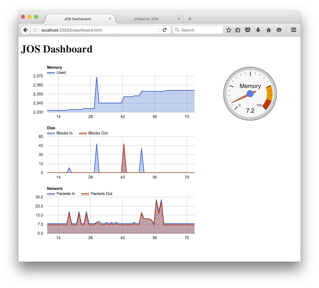
After that,
you should see the JOS dashboard
at http://host:port/dashboard.html.
Hint: take a look at the values in kern/sysinfo.c.
This completes the lab. As usual, in answers-lab6.txt,
don’t forget to
write up your answers to the questions,
how much time you spend on this lab, and
the names of your team members if you work in pairs.
Before handing in, use git status and git diff to examine your changes. When you’re ready, commit your changes, type make handin, and upload the tarball through the course dropbox.