Boolean Logic & Skills
Our first step in building a computer is learning about circuits! In order to be able to reason about and build circuits, we need to first learn a little bit about boolean logic. Because we have to cover the basics of boolean logic, and set up the context for the course, and set up the context for the projects, this reading will be slightly longer than most in this course. We estimate that it will take you 20-30 minutes maximum to complete.
What is boolean logic?
Boolean logic is a definition built around two boolean values: true and false. You’ve actually used these boolean values in Java before! It turns out that having a formal way to reason about these values is super useful when building hardware, and defining this reasoning is our first step towards building a computer.
Why two values? An important abstraction
It turns out that the signals on the physical wires in our computer hardware could have any number of volts from 0 - 5 continuously. For our purposes, we are going to choose an abstraction that only has 2 values: a “high” signal (near 5 volts) or a “low” signal (near 0 volts). You might be wondering, why limit ourselves to only two values, high and low? In reality most hardware is designed to have an abstraction of just two values of voltage. This significantly reduces errors in hardware, and ends up being easier to reason about (by allowing us to use boolean logic).
As we noted above, boolean logic traditionally has only two values as well: true and false. We can then map our two-value voltage system to these two values - “high” signals correspond to true, and “low” signals correspond to false. Additionally, often the binary digits 1 and 0 are used to refer to values in this system, with 1 being a high signal/true value, and 0 being a low signal/false value. Lots of different ways of referring to the same thing!
This is the first of many powerful abstractions we will come across when building a computer - our discrete 2-value system allows us to not worry about the actual voltage reading when interpreting a wire’s value.
Boolean algebra
Boolean algebra is a set of operations for combining boolean values. Just like the algebra you’ve learned in school has operations to combine decimal values (e.g. 3 + 5 = 8) boolean algebra defines a set of operations for combining boolean values. A boolean operation is specified by something called a truth table. A truth table enumerates every possible combination of inputs for that boolean operation, and then specifies what the output should be for each input combination. Three common boolean operations are:
x And y - outputs true (1) only if both x and y are true. Truth Table:
| x | y | out |
| 0 | 0 | 0 |
| 0 | 1 | 0 |
| 1 | 0 | 0 |
| 1 | 1 | 1 |
x Or y - outputs true (1) only if at least one of x or y are true. Truth Table:
| x | y | out |
| 0 | 0 | 0 |
| 0 | 1 | 1 |
| 1 | 0 | 1 |
| 1 | 1 | 1 |
Not x - Outputs true (1) if x is false (0) and false if x is true. Truth table (note how we only have 2 rows now because there are only 2 possible values for a single input):
| x | y | out |
| 0 | 1 | 0 |
| 1 | 0 | 1 |
Note that you can define a boolean operation both by a written description and by using a truth table. The latter is a much more explicit way of defining a function - it tells you exactly what that function does for every possible output combination.
Boolean expressions are combinations of boolean operators that evaluate to a value. We can evaluate a boolean expression by applying the truth table over and over until we are left with a single value.
Example: Not(0 Or (1 And 1)) = Not (0 or 1) = Not (1) = 0
Boolean Functions
We can also define our own boolean functions! All we need to do is give names to the inputs for our function, and then specify what the outputs are for those inputs. This can be specified as either a truth table or as a boolean expression of our inputs!
For example we could specify a function as: f(x, y, z) = (x And y) Or (Not(x) And z)
Now someone can figure out the output for a combination of inputs by plugging the input values into our boolean expression. We can also use this boolean expression to build up a truth table for our boolean function. All we need to do is evaluate our boolean expression for each row of our truth table.
For example, the second row in the below truth table is evaluated as follows:
f(0, 0, 1) = (0 And 0) Or ((Not 0) And 1)
           = 0 Or ((Not 0) And 1)
           = 0 Or (1 And 1)
           = 0 Or 1
           = 1
See if you can fill out the remaining rows in our truth table (full truth table is given in the “Exercise Solutions” section at the bottom of this reading).
f(x, y, z) = (x And y) Or (Not(x) And z)
| x | y | z | out |
| 0 | 0 | 0 | |
| 0 | 0 | 1 | 1 |
| 0 | 1 | 0 | |
| 0 | 1 | 1 | |
| 1 | 0 | 0 | |
| 1 | 0 | 1 | |
| 1 | 1 | 0 | |
| 1 | 1 | 1 |
Boolean logic can describe hardware designs
Why are we learning about boolean functions? It turns out that computer circuits can be represented by boolean functions! Values (such as 0 and 1) are carried on wires, operators (such as And) map to physical circuit gates, and combinations of wires and physical circuit gates build our hardware devices. When we say x And y, we are describing a physical circuit, with a wire corresponding to the x input, a wire corresponding to the y input, and an And gate connecting the two input wires and sending an output signal on another wire. This is the basis of our work for the first few weeks of this class.
Simplifying boolean functions
Simplifying boolean functions is actually a top priority when designing hardware. Simpler boolean functions require less wires and gates to implement which ultimately lead to cheaper and faster hardware. One way of simplifying boolean functions is by applying boolean identities to a boolean function. These identities define equivalent boolean expressions that allow us to manipulate our boolean functions and potentially create simpler expressions. A non-exhaustive list is:
- Commutativity
(x And y) = (y And x)(x Or y) = (y Or x)
- Associativity
(x And (y And z)) = ((x And y) And z)(x Or (y Or z)) = ((x Or y) Or z)
- Distributive Property
(x And (y Or z)) = (x And y) Or (x And z)(x Or (y And z)) = (x Or y) And (x Or z)
- De Morgan's Law
Not(x And y) = Not(x) Or Not(y)Not(x Or y) = Not(x) And Not(y)
- Double Negation
Not(Not(x)) = x
Let’s say we have the function f(x, y) = Not(Not(x) And Not(y)). We can apply identities to potentially simplify that function:
Not(Not(x) And Not(y)) **use De Morgan’s Law**
= Not(Not(x)) Or Not(Not(y)) **use double negation**
= x Or y
Another way of simplifying our expression is to build up a truth table for it and see if it matches any functions we know already.
f(x, y) = Not(Not(x) And Not(y))
| x | y | out |
| 0 | 0 | 0 |
| 0 | 1 | 1 |
| 1 | 0 | 1 |
| 1 | 1 | 1 |
That looks exactly like the truth table for x Or y! We won’t ask you to do too much simplifying in this course, but it is an important part of hardware design so we thought it would be worth mentioning!
Boolean function synthesis
We’ve talked about creating a truth table from an existing boolean expression, now let’s talk about creating a boolean expression from an existing truth table! This is an important part of hardware design - often we will know the outputs we want for each set of inputs (i.e. we know the truth table), and then we have to create a boolean expression so that we can define the logic gates for our function and ultimately build the hardware corresponding to it. Suppose we have the following truth table for our function:
| x | y | z | out |
| 0 | 0 | 0 | 1 |
| 0 | 0 | 1 | 0 |
| 0 | 1 | 0 | 1 |
| 0 | 1 | 1 | 0 |
| 1 | 0 | 0 | 1 |
| 1 | 0 | 1 | 0 |
| 1 | 1 | 0 | 0 |
| 1 | 1 | 1 | 0 |
Our plan is going to be this: first, for each row where the output is "true", define a function that is "true" for that row and only that one row. Then, since we have expressions for each of the true rows, we can combine them together to get an expression for the entire truth table.
It turns out we can describe any row in terms of And and Not gates. For each input, if a 1 appears in the row, we will use just the input, and if a 0 appears we will negate the input. Then we can combine our inputs with And gates.
For example: row1(x, y, z) = Not(x) And Not(y) And Not(z)
We can see that row1 is only true for the first row in our truth table!
| x | y | z | out | row1 |
| 0 | 0 | 0 | 1 | 1 |
| 0 | 0 | 1 | 0 | 0 |
| 0 | 1 | 0 | 1 | 0 |
| 0 | 1 | 1 | 0 | 0 |
| 1 | 0 | 0 | 1 | 0 |
| 1 | 0 | 1 | 0 | 0 |
| 1 | 1 | 0 | 0 | 0 |
| 1 | 1 | 1 | 0 | 0 |
Let’s do the same for the other "true" rows:
row3 = Not(x) And y And Not(z)
row5 = x And Not(y) And Not(z)
| x | y | z | out | row1 | row3 | row5 |
| 0 | 0 | 0 | 1 | 1 | 0 | 0 |
| 0 | 0 | 1 | 0 | 0 | 0 | 0 |
| 0 | 1 | 0 | 1 | 0 | 1 | 0 |
| 0 | 1 | 1 | 0 | 0 | 0 | 0 |
| 1 | 0 | 0 | 1 | 0 | 0 | 1 |
| 1 | 0 | 1 | 0 | 0 | 0 | 0 |
| 1 | 1 | 0 | 0 | 0 | 0 | 0 |
| 1 | 1 | 1 | 0 | 0 | 0 | 0 |
Now we just need to combine our different row expressions to get our final expression (we'll name our function f). Note that to get f, we want a 1 to appear in a row if there is at least one 1 in one of the other rows. What operation does “at least” remind you of? Yup, an Or operation! We combine our row expressions using Or to get our final expression for f.
f(x, y, z) = row1 Or row2 Or row3
f(x, y, z) = (Not(x) And Not(y) And Not(z)) Or (Not(x) And y And Not(z)) Or (x And Not(y) And Not(z))
That is a totally correct boolean expression! We can simplify that expression if we want to (it is pretty long...), but I think it’s important to point out that the expression above correctly describes the truth table we started with; it’s just maybe a little more verbose than we would like it to be. From here we can simplify using boolean identities (omitting the steps because it is not the focus of this section), resulting in the final expression:
f(x, y, z) = Not(z) And (Not(x) Or Not(y))
It’s pretty neat that this process works for every possible truth table/boolean expression out there! To summarize the process, to get a boolean expression for a given truth table we:
- Create an expression for each “true” row in the truth table using
AndandNot. - Combine these individual expressions with
Or. - Now we have a completely correct expression for the truth table! We can simplify further if we’d like to (often hardware designers will want to do this).
More ways to describe hardware
Logic Gates
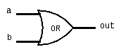
As we said before, logic gates implement boolean operations in hardware. We can actually draw diagrams of these using conventional symbols (see Chapter 1 of the textbook for more of these symbols).
Example: a Or b
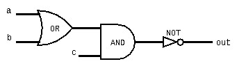
We can also combine operations by wiring logic gates together.
Example: Not((a or b) And c)
Hardware Design Languages (HDLs)
In this class, we will also work with a Hardware Design Language. These are programming languages used to specify hardware components and how they’re connected. There are many different flavors of hardware design languages, but in this course we will use a fairly simple one called “HDL”.
The HDL files we use in this class will all have a similar structure. They will start with a comment describing the expected behavior, then a section naming the input and output wires for the logic chip, and finally a parts section where you will define the components/implementation of the chip.
/**
* Exclusive-or gate:
* out = not (a == b)
*/

CHIP Xor {
  // Names of inputs/outputs
  IN a, b;
  OUT out;

  PARTS:
  // Put your code here:

}
Your implementation for each chip will likely make use of other chips to build a more complex chip. In order to reference another chip, you specify the name of the chip and then which wires should be used for the inputs/outputs of the chip, for example, we could specify an And gate in our chip as follows:
CHIP Xor {
  ...
  PARTS:
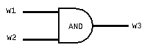
  And (a=w1, b=w2, out=w3);
}
This creates an And gate that has w1 and w2 as inputs and the output connected to w3. An equivalent circuit diagram would be:
HDL is different from a programming language like Java in that HDL is what we call a “declarative” language. By this, we mean that the order of statements in an HDL program does not matter. This might be quite jarring coming from a language like Java where the order of the statements you write really matters! Think of HDL as describing a circuit diagram; the order in which you write down the descriptions/components of that diagram doesn’t matter as long as the description has the same components and connections. For example, the following two HDL programs are equivalent:
// Program 1
Not(in=a, out=nota);
And(a=a, b=nota);

// Program 2, which is equivalent to program 1
And(a=a, b=nota);
Not(in=a, out=nota);
Though in the second example it looks like nota is used before it is declared, the HDL compiler is really smart and will end up creating the same circuit for both of these programs!
You’ll likely want to refer to this HDL survival guide (also accessible from the "Resources" page) a lot when first using HDL in the projects (your instructor constantly referred to this guide when they were first learning the projects too :) ).
Multi-bit Buses in HDL
Sometimes we will want to manipulate groups of wires and pass them around together to various logic chips. We call each group of wires a “bus”, and we often refer to each wire in these buses as a “bit”. HDL provides a convenient way of defining and referring to buses. Here’s an example of an And4 chip, which takes in two 4-bit buses and returns a 4-bit bus that is the result of taking the And of each corresponding wire of the input buses.
/**
 * Bit-wise And of two 4-bit inputs
 */
CHIP And4 {
  IN a[4], b[4];
  OUT out[4];

  PARTS:
  And (a=a[0], b=b[0], out=out[0]);
  And (a=a[1], b=b[1], out=out[1]);
  And (a=a[2], b=b[2], out=out[2]);
  And (a=a[3], b=b[3], out=out[3]);
}
Project 1 Overview: It all starts with Nand
In Project 1, you will build increasingly complex logic gates that will form as the building blocks of our computer. As you implement chips, you will be able to use those chips to build other chips, both in Project 1 and in future projects (the project specification will have more details).
To get you started, we give you just one gate: the Nand gate. Nand stands for “Not And” and is essentially the opposite of an And gate. Here is the truth table for a Nand b:
| a | b | out |
| 0 | 0 | 1 |
| 0 | 1 | 1 |
| 1 | 0 | 1 |
| 1 | 1 | 0 |
It turns out that every boolean function/logic gate that is used in your computer can be recreated using only Nand gates!! Why can Nand be used to define every boolean function? Every boolean function can be represented by a truth table, and if you recall our process for synthesizing boolean functions from truth tables, we only needed three gates: Not, And, and Or. We can represent Or using Not and And by applying De Morgan’s law:
a Or b = Not(Not(a) And Not(b)).
So really every function can be represented by Not and And! Now we just need to be able to define Not and And in terms of Nand. First we can define And in terms of Not and Nand:
a And b = Not(a Nand b).
Finally we can define Not in terms of Nand(write out a truth table if the follow equivalency doesn't make sense):
Not a = a Nand a
This means that every truth table, and consequently every boolean function and every hardware gate, can ultimately be represented in terms of Nand! This is pretty cool, but we don’t recommend you only write Nand gates in your implementations on the projects (if you think about it, since you will define your first few chips in terms of Nand, and then later chips in terms of those chips, and so on and so forth, you’re entire computer will essentially be built on top of Nand gates).
Project example: Xor
To finish, let’s work through an example gate Xor. This example will be similar to the process you will repeat throughout Project 1. We will define the behavior as follows:
Xor(a, b) returns a 1 if the inputs are opposite of each other and a 0 if they are the same.
Our first step is to build a truth table for this function:
| a | b | out |
| 0 | 0 | 0 |
| 0 | 1 | 1 |
| 1 | 0 | 1 |
| 1 | 1 | 0 |
Next we can come up with an expression for that truth table using our synthesis process described earlier.
row2 = Not(a) And b
row3 = a And Not(b)
Xor(a, b) = row2 Or row3
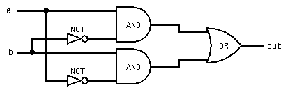
          = (Not(a) And b) Or (a And Not(b))
If we want we can then draw out a circuit diagram for our function:
Lastly, we just have to translate this function/diagram into HDL syntax:
CHIP Xor {
  IN a, b;
  OUT out;

  PARTS:
  Not(in=a, out=nota);
  Not(in=b, out=notb);
  And(a=a, b=notb, out=x);
  And(a=nota, b=b, out=y);
  Or(a=x, b=y, out=out);
}nota, notb, x, y) to store the results of intermediate computations - this is something you will make heavy use of in your projects.
Exercise Solution
Full truth table for f(x, y, z) = (x And y) Or (Not(x) And z)
| x | y | z | out |
| 0 | 0 | 0 | 0 |
| 0 | 0 | 1 | 1 |
| 0 | 1 | 0 | 0 |
| 0 | 1 | 1 | 1 |
| 1 | 0 | 0 | 0 |
| 1 | 0 | 1 | 0 |
| 1 | 1 | 0 | 1 |
| 1 | 1 | 1 | 1 |