Reading 5: Sequential Logic
So far, we've only dealt with what is called combinational logic in circuits. Combinational logic allows us to perform nearly instantaneous calculations, but you may have noticed we have not discussed keeping track of time in our circuits. This reading introduces you to sequential logic at a high level, which will allow us to incorporate the notion of time in our computer.
Why Sequential Logic?
The programs you've written in the past had some order in which the lines of code are executed. In order to execute programs in a particular order, our computer needs some notion of time. So far, our circuits do not have a strong notion of time. Take the following circuit for instance:
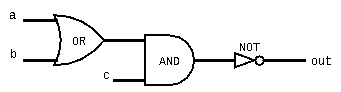
Our brains may like to think about this circuit in a sequential manner. We know that the Or gate functions before the And gate, which functions before the Not gate. In reality, everything in the above circuit happens at nearly the same time. Think of out being linked to a, b, and c by the circuit logic, such that when any input changes, out also changes almost immediately because it is linked to those inputs. In reality, there are very slight delays in circuit gates that are important to consider.
The Problem
One problem with our circuit above is that since out updates nearly instaneously when the inputs change, there is no buffer time that we can use to change the input values. For instance, let's say our values are as follows: a = 0, b = 1, and c = 0. Based on our function above, this would mean that out = 1. Let's say we wanted to change our inputs, such that c = 1 and b = 0. Note that after this change is in place, out should still be 1, but if we change c first, there is a brief point where out = 0, which we don't want. This problem is further exacerbated by the slight delay logic gates that occurs.
We could try to choose which input we change first, but since this relies not only on our circuit but also on the current values, there is no way to specify a general rule for how to do this. And choosing the order we change the inputs doesn't account for the delay caused by logic gates.
Reusing Outputs as Inputs
To explore why we need a new notion of time, let's consider what we might want to do that we can't already with only combinational logic. For our example, let's say we wanted to implement the following sequential pseudocode (for now, assume that x is just one bit):
// Remember that ~ negates (flips) the bits of its input
x = ~x
We may come up with the following HDL code to represent the first line of the pseudocode:
Not(in=x, out=x);
Which would result in the following circuit diagram:
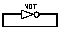
If our circuits are almost instantaneous, then the above circuit doesn't make sense. As soon as the output changes (e.g., from 0 to 1), the input immediately changes, which immediately changes the output, which immediately changes the input, and so on. The output continues to fluctuate between 0 and 1. With the above circuit, we can't complete the Not operation just once because we have no notion of what “once” means. Ideally, we'd be able to have x maintain its state until we tell it to change and change only when we tell it to change.
Representing Time: Clock Signals
The first question we will address is how to physically represent time in hardware. The most common way of doing this is using what we will call a clock signal. A clock signal is a signal that changes its frequency at a set time rate, allowing us to rely on it to keep track of time. For example, a clock signal may alternate between emitting a low signal for 2 nanoseconds and then a high signal for 2 nanoseconds. We can now view each “cycle” (the period of time with both a low and a high signal) as one unit of time in hardware (in this case, 4 nanoseconds).
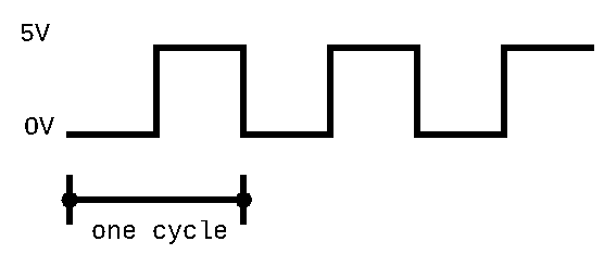
Note that by changing how long we emit the low and high signals in our clock signal, we can effectively change how long a unit of time is. The key takeaway here is that we represent time with a clock signal that alternates between high and low signals, and that one unit of time (or clock cycle) in our hardware will consist of a period of time equal to one low signal and one high signal.
Using Clock Signals: Flip Flops
Now that we have a way to represent time, we need a way of using that representation in our circuits. For this, we will introduce a new type of circuit: the data flip flop, or DFF for short. DFFs have three key parts: An input, an output, and a connection to the clock signal. Note how in circuit diagrams we don't explicitly create a wire for the clock signal. Instead, you'll often see triangles drawn on the edge of the circuit indicating that the circuit is connected to the clock.
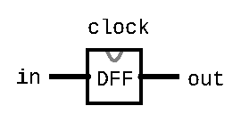
For a given time period, the data flip flop captures the value of the input at a predefined part of the clock signal (usually when the signal transitions from low to high). It then uses this value as the output for the DFF until the next point at which it captures the signal. This is an important abstraction. By choosing to only capture the input at one point within the clock signal, it essentially means that the output can only change once per clock cycle. This abstraction allows us to create circuits that change based on the notion of time.
We now have a way of making noninstantaneous changes to our circuits. DFFs introduce a delay when changes to the input affect the output. More specifically, the output for a DFF at time t is determined by the inputs at time t-1 since the output only changes when transitioning to the next time period.
The Road Ahead
Don't fret if you're still feeling confused about sequential logic, clock signals, and DFFs. This reading is merely meant to introduce you to these ideas. In lecture, we will spend more time reinforcing these ideas using concrete examples, which will build on this introduction.
Notice how we also still haven't shown how we can implement the pseudocode that we showed earlier in the reading:
x = ~x
DFFs allow us to build the hardware to support this pseudocode, but there are many more details that we will need to learn in order to do so. In the next few weeks, we will use DFFs as the starting point to build core, complex components of our computer, including memory, registers, and ultimately our CPU.