Project 2: Study Skills Inventory & Boolean Logic
Due Date: Thursday, April 7th, 2022 at 11:59pm PDT
Learning Objectives
- Assess your existing study skills and consider which areas you want to improve in.
- Practice the principles of Boolean logic and learn about fundamental logic gates that form the basis of all modern computers.
Part I: Study Skills Inventory (5 points)
Navigate to the Project 2 assignment on Canvas (linked here). Download the document template titled p2_Study Skills Inventory & Boolean Logic.docx. Open the document, read the instructions on the first page, and estimate the amount of time you think it will take you to complete this project.
Then, complete the Study Skills Inventory online at https://forms.gle/PTezNdg3hnR3gh5p6. The Study Skills Inventory is meant to help you reflect on your current academic behaviors, strategies, and practices. Answer the questions honestly. We are not going to be judging or grading you based on your answers. The goal is to help you identify areas where you feel are strengths and areas of improvements in your study skill practices. You will be asked to submit this same Study Skill Inventory at the end of the course.
Submission: For this part of the project, simply submit the Google Form linked above. Contact the course staff if you have trouble accessing the form.
Part II: Boolean Logic (15 points)
Background
A typical computer architecture is based on a set of elementary logic gates like And, Or, Mux, etc., as well as their bit-wise versions And16, Or16, Mux16, etc. (assuming a 16-bit machine). This project engages you in the construction of a fundamental set of logic gates. These gates form the elementary building blocks from which more complex chips will be later constructed.
Pulling From Your GitLab Repository
In your GitLab repository, you will see a new folder, /projects/p2/. Since the updated code currently only exists in your server (sometimes called the remote or origin) repository, we will need to pull the code from the server to your local repository. To do this, navigate to your local repository, (e.g., cse390b-22sp-ericfan), and run the command git pull, which pulls your code from your GitLab repository stored in the GitLab server. If successful, you'll see the /projects/p2/ directory in your local repository.
Overview
In this project, you will build the following logic gates, yielding a basic chipset. The only building blocks you can use in this project are the primitive Nand gate and any logic gates that you've already implemented. We will gradually build on top of them. For that reason, we highly recommend that you go in the order given below (e.g., the Not gate should only be built from Nand gates, And should be built from Not and Nand gates, etc.).
| Chip Name | Description | Test Script | Expected Output |
|---|---|---|---|
| Nand | (Primitive) Nand Gate | ||
| Not | Not gate | Not.tst | Not.cmp |
| And | And gate | And.tst | And.cmp |
| Or | Or gate | Or.tst | Or.cmp |
| Xor | Xor gate | Xor.tst | Xor.cmp |
| Mux | Multiplexor | Mux.tst | Mux.cmp |
| DMux | Demultiplexor | DMux.tst | DMux.cmp |
| Not16 | 16-bit Not gate | Not16.tst | Not16.cmp |
| Mux16 | 16-bit Multiplexor | Mux16.tst | Mux16.cmp |
| Or8Way | Or gate between 8 inputs | Or8Way.tst | Or8Way.cmp |
| Mux4Way16 | 16-bit, 4-way Multiplexor | Mux4Way16.tst | Mux4Way16.cmp |
Contract
When loaded into the supplied Hardware Simulator, your chip design (modified .hdl (Hardware Descriptive Language) program), tested on the supplied .tst (test) script, should produce the outputs listed in the supplied .cmp (compare) file. If this is not the case, the simulator will let you know. This contract must be satisfied for each chip listed above, except for the Nand chip, which is considered primitive, and thus there is no need to implement it.
Resources
The relevant reading for this project is Chapter 1 and Appendix A. Specifically, all the chips described in Chapter 1 should be implemented in the Hardware Description Language (HDL) specified in Appendix A. Another resource that you will find handy in this and in all subsequent hardware projects is this HDL Survival Guide, written by Mark Armbrust.
For each chip, we supply a skeletal .hdl file with a place holder for a missing implementation part. In addition, for each chip, we supply a .tst test script that instructs the hardware simulator how to test it, and a .cmp containing the correct output that this test should generate. Your job is to complete and test the supplied skeletal .hdl files.
You will find the supplied Hardware Simulator and all the necessary project files in the tools/ directory and in the projects/p2/ directory of your repository, respectively.
Part II Tips
First, make sure you've followed the setup instructions in Project 1!
Built-in chips: The Nand gate is considered primitive, and thus, there is no need to implement it. Whenever a Nand chip-part is encountered in your HDL code, the simulator automatically invokes the built-in tools/builtInChips/Nand.hdl implementation. We recommend implementing all the other gates in this project in the order in which they appear in the table above. However, note that the supplied Hardware Simulator features built-in implementations of all these chips. Therefore, you can use any one of these chips before implementing it. The simulator will automatically invoke their built-in versions (to invoke the built-in chips, rename or move the unimplemented .hdl file in your /projects/ directory to signal to the Hardware Simulator to use the built-in chip).
For example, consider the supplied skeletal Mux.hdl program. Suppose that for one reason or another, you did not complete the implementation of Mux, but you still want to use Mux chips as internal parts in other chip designs. You can easily do so, thanks to the following convention. If the Hardware Simulator fails to find a Mux.hdl file in the current directory, it automatically invokes the built-in Mux implementation, which is part of the supplied simulator's environment. This built-in Mux implementation has the same interface and functionality as those of the Mux chip described in the book. Thus, if you want the simulator to ignore one or more of your chip implementations, simply rename the corresponding .hdl file or remove it from the directory. When you are ready to develop this chip in HDL, rename the .hdl to its original name or put the appropriate
Remember to peruse Chapter 1 of the online textbook before you start implementing chips. It breaks down each chip's interface in depth and often describes strategies for implementation.
You'll also want to refer to Appendix A periodically to learn about the HDL. In particular, we recommend you read section A.5.3 "Buses" before getting to the 16-bit chips, where you'll need to use wires that consist of multiple bits (called "buses"). When you see a wire declared as in[16], think of that as a "bundle" of 16 wires—each of which can be individually referenced with in[0], in[1], ... in[15].
When you test your code by running the Hardware Simulator, loading the corresponding .tst script and pressing Run, it may indicate a "comparison error." When this happens, we recommend going to your file explorer and searching for: (1) a corresponding .cmp file that shows the inputs being tested and expected outputs of your chip, and (2) a corresponding .out file that shows the actual outputs of your chip when tested. Given that information, a good next step is tracing through your design with those inputs to see why it produced the value it did.
Additional Chips
The following additional chips (described in Chapter 1) can be used in future projects, but you are not required to implement them (instead, you can rely on the built-in versions). The intention is to give you extra tools to make future projects easier without requiring you to spend time implementing them.
- And16
- Or16
- Mux8Way16
- DMux4Way
- DMux8Way
Tools
All the chips you'll implement in Projects 1-5 can be implemented and tested using the supplied Hardware Simulator. Instructions for opening the Hardware Simulator are:
- Mac and Linux (enter these commands into your terminal):
- Navigate to your repository root (e.g., Run
cd cse390b-22sp-ericfan) - Enter the
tools/directory. Runcd tools - Make everything "executable." Run
chmod +x *.sh *.bat - Run the Hardware Simulator. Run
./HardwareSimulator.sh - At this point, the Hardware Simulator should appear in a new window
- Navigate to your repository root (e.g., Run
- Windows (run these in a GitBash shell. If you get an error complaining about an unknown command 'java', you may have to install Java and then restart GitBash):
- Navigate to your repository root (e.g., Run
cd cse390b-22sp-ericfan) - Enter the
tools/directory. Runcd tools - Make everything "executable." Run
chmod +x *.sh *.bat - Run the Hardware Simulator. Run
./HardwareSimulator.bat - At this point, the Hardware Simulator should appear in a new window!
- Navigate to your repository root (e.g., Run
tools/ directory).
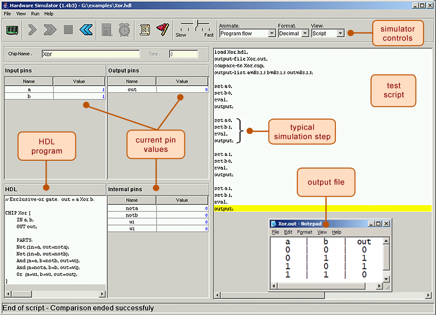
Here is a screenshot of testing a Xor.hdl chip implementation on the Hardware Simulator:
Examples
The following are complete reference implementations of two chips in the assignment. Feel free to copy and paste them
into the code you submit on GitLab. These are provided to help you get familiar with the HDL syntax and let you
experiment with the tools before working on the rest of the assignment. Note that you will need a working
And.hdl, Or.hdl, and Not.hdl, or you will need to rename those files so the simulator uses built-in versions (as
demonstrated in class).
Xor.hdl
An Xor gate returns 1 when one, and only one, of its inputs is 1—if neither or both are 1, the gate returns 0. You can learn more about this gate in Chapter 1.
CHIP Xor {
  IN a, b;
  OUT out;

  PARTS:
  // Put your code here:
  Not (in=a, out=nota);
  Not (in=b, out=notb);
  And (a=a, b=notb, out=x);
  And (a=nota, b=b, out=y);
  Or (a=x, b=y, out=out);
}
Mux.hdl
A Multiplexor ("Mux") has two "data" inputs and one "selector" input. If the selector input is 0, the chip returns whatever it gets from the first data input, and if the selector is 1, the chip returns whatever it gets from the second data input. This is a fundamental tool allowing the computer to "choose" which of two possible values it should use. You can learn more about this gate in Chapter 1.
CHIP Mux {
  IN a, b, sel;
  OUT out;

  PARTS:
  // Put your code here:
  Not (in=sel, out=notsel);
  And (a=a, b=notsel, out=anda);
  And (a=b, b=sel, out=andb);
  Or (a=anda, b=andb, out=out);
}
Submitting Part II
To submit Part II, make sure you commit and push your changes, then tag them as project-2 and push that tag as well:
git add .(Stage all your changes)git commit -m "Finish project 2"(Bundle those changes as a commit)git push(Push that commit to the GitLab server)git tag project-2(Add the project-2 tag to that last commit)git push --tags(Push the tag to the GitLab server)
Lastly, verify that the tag and all your code is uploaded correctly by checking on gitlab.cs.washington.edu.
Part III: Project 2 Reflection (5 points)
As mentioned in Project 1, each project will include a reflection component. In the document p2_Study Skills Inventory & Boolean Logic.docx, record how long the project took you in reality and write a short written reflection about your experience completing this project.
Submission: Once you have completed Part III of the project, save the document as a PDF and submit the document on Gradescope under the assignment named Project 2: Study Skills Inventory & Boolean Logic.
Conclusion
Project 2 will be completed once you have completed the Study Skills Inventory, submitted this document to Gradescope, and pushed your GitLab changes with the project-2 tag.