Implementation of Control
Overview
We'll build a simple stack machine, using a number of implementations of control:
- An implementation directly in logic gates
- An implementation using a single PLA.
- An implementation using two levels of control, a PLA and specialized ALU control.
This machine is really too simple to show off the advantages of the last two approaches,
but it conveys the idea and lets us get through it in one lecture. (See Chapter 5.3 in
the text for a discussion of these approaches applied to the MIPS ISA.)
The Simple Stack Machine
The machine has 6.5 instructions: add, sub, mult, div, pop, push, and stop,
with 8-bit opcodes 0x00, 0x01, 0x02, 0x03, 0x04, 0x05, and 0x08 respectively.
All instructions other than push are 8-bits long, and consist of just the opcode.
A push instruction is 32-bits long: an 8-bit opcode followed by 24-bits of immediate data.
A Sample Program
One way to express programs for this machine is as a postfix expression. For instance,
computes 4!. (The '$' means stop.) The machine code is:
05000001   # push 0x000001
05000002   # push 0x000002
02         # mult
05000003   # push 0x000003
02         # mult
05000004   # push 0x000004
02         # mult
08         # stop
Here's a second program we'll use for testing: 1 2 3 4 5 + - * / $
The Datapath and Control
Here's the datapath we'll use:
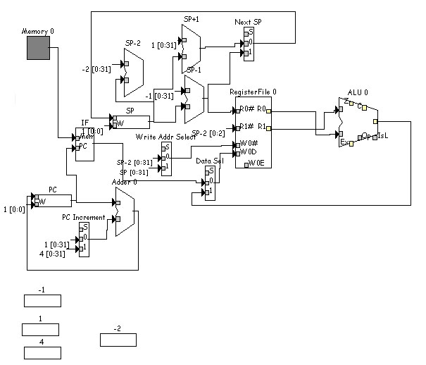
(Those boxes near the bottom are constant registers.) We use the register file for
the stack; the memory holds the program (only). In this implementation we don't worryabout
little annoyances like exceeding the capacity of the stack, or program bugs like
issuing operations when there are not enough operands on the stack.
Six components require control signals: the register file (write enable),
Write Address Select mux, Next SP mux, Data Sel mux, PC Increment mux,
and the ALU (operation).
(Note that SMOK ALU's have ALU ops that can be changed by the user. That can be convenient for
some models. For this model the default mapping is fine.)
Method 1: Direct Implementation in Logic Gates
Method 2: Truth-Table -> PLA
The stop instruction is easily implemented as a
Halt component, and so we'll just assume that's how its implemented
and not worry about it further.
For the other instructions, here's the truth table for control:
| Opcode (input) | W0E | Write Addr | Next SP | Data Sel | PC Incr | ALU op |
|---|
| + 0000 0000 | 1 | 0 | 1 | 1 | 0 | 00 |
| - 0000 0001 | 1 | 0 | 1 | 1 | 0 | 01 |
| * 0000 0010 | 1 | 0 | 1 | 1 | 0 | 10 |
| / 0000 0011 | 1 | 0 | 1 | 1 | 0 | 11 |
| pop 0000 0100 | 0 | X | 1 | X | 0 | XX |
| push 0000 0101 | 1 | 1 | 0 | 0 | 1 | XX |
'X' means "don't care".
This can be encoded directly in a PLA.
The file stackControlOnePLA.smokpla
in the .zip file shows the encoding for this truth table.
Method 3: Two Levels of Control
The truth table above is big. Plus, the first four rows are identical, except for the
ALU op control. We can simplify the control by splitting out the detailed computation
of the ALU op control, using the PLA just to indicate how it should be computed.
Doing that we get:
| Opcode (input) | W0E | Write Addr | Next SP | Data Sel | PC Incr | ALUCtrl |
|---|
| 0000 00XX | 1 | 0 | 1 | 1 | 0 | 1 |
| pop 0000 0100 | 0 | X | 1 | X | 0 | 0 |
| push 0000 0101 | 1 | 1 | 0 | 0 | 1 | 0 |
The ALUCtrl signal is used as input to another piece of control, the ALU control. It takes the low
order two bits of the opcode as input as well.
If ALUCtrl is 1, ALU Control passes the low order opcode bits to the ALU as the op control.
(Unfortunately for the strength of this example, if ALUCtrl is 0 it doesn't matter what the ALU control
does, because the ALU output won't be used. In general, though, it would do something different than pass
on the low order opcode bits.)
The file stackControlTwoPLA.smokpla
in the .zip file shows the encoding for this truth table.