CSE 378
Quiz Section #5
SMOK Tutorial and Reference
·
SMOK Model Construction Tutorial - http://www.cs.washington.edu/homes/zahorjan/homepage/Tools/SMOK/ExampleModel.htm
·
Fun with ALU’s – Replace the ADDER in the Model
constructed above with an ALU and connect the Op bits to constant registers to
make sure it adds.
·
Fun with Containers – Convert your model above
into a FancyStepper Container.
It should have two inputs
o StepAmount
– the amount by which to step each iteration
o StepOp
(3 bits) – the operation to apply in each iteration
and one output, the resulting value for each iteration (this can be initialized to 1). For example, when the FancyStepper operates with StepAmount = 2 and StepOp set to multiply, and the inputs do not change, then the resulting output for each cycle should be 1, 2, 4, 8, 16, 32, 64, …
· Fun with PLA’s – Add a (very) simple PLA to the container above, so that when StepOp = 111 the counter is reset to 1, otherwise you pass the control bits on to the ALU (hint: you will need a MUX).
· Messing with Memory – Practice adding a memory component to a SMOK model, and loading a .smokmem file into it (you will need to do this to load your programs into a SMOK machine simulation). Practice connecting a Memory to IF and Memory Interface components. (Note: you do not have to worry about the #B and the Sz Ports on the Memory Interface)
SMOK Home Page: http://www.cs.washington.edu/homes/zahorjan/homepage/Tools/SMOK/
SMOK Component Reference: http://www.cs.washington.edu/homes/zahorjan/homepage/Tools/SMOK/ComponentRef/
SMOK Reference:
Well, we have studied different ways to implement a processor. Obviously, we will now ask you to build some. :) But how? For this, we will use the SMOK tool to build and simulate the execution of our machines. The one important rule to remember about SMOK however…
Be careful with your work!
Even though SMOK seems to be stable right now, you never really know. Save often, and in many different files.
The basic idea of building a machine in SMOK is to place a number of components (such as an ALU, a register, an OR-gate, etc.), and then to connect those components with wires in a way that they will perform some useful operation.
Always remember that an unconnected connection is equivalent to a 0 signal along that connection.
Where Can I Find It?
The latest version of SMOK should be installed on all the general undergrad lab machines. To find it, simply go to Start à Programs à Desktop Tools à CSE378. You can also work from home, if you so desire – just get the installer from the SMOK homepage (linked from the cse378 page).
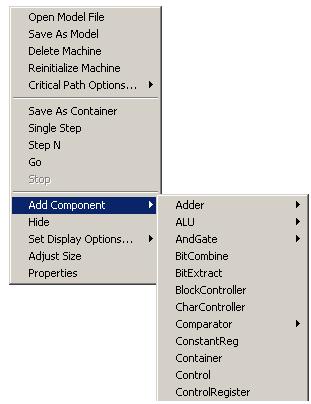
Placing Components
If you right-click on a blank area of your working space, then you will see a menu of general-use options that come in very helpful at times. One of the options is “Add Component”. Not surprising is the fact that it gives you a list of components (sorted alphabetically) that you can place in your workspace. Some components have normal, slow, and fast flavors – the faster versions propagate their calculations quicker, but cost more transistors to create. In these cases, sticking to the regular versions is a safe bet.
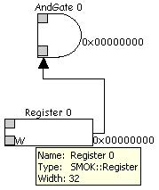
Connecting Components
Well, suppose we now have two components, say an AND-gate and a register, happily sitting around and doing absolutely nothing. What now? Well, let’s connect the output of the register to the AND-gate. In order to do this, we need to click on one of the input ports of the AND-gate (a gray box), and then on the output port of the register. Note that when no ports are visible, clicking on the component itself will suffice.
Widths
Every component and every wire has an associated width – how many bits that component can work with, or how many bits that wire can carry. By default, all widths are 32. Note that, as in the case of the register above, the width is the number of bits the component can store internally. The wire has the same width as the output port (or the component itself) from which it leads. The input port can select how many bits wide it is (how many bits it will accept), and from which bit number of the wire to read. Again, unconnected bits are simply accepted as 0.
Properties
The width is just one of the many possible properties that an object can have. Setting these properties can be very useful (or even mandatory) in making the component do exactly what you want it to do. To access these, simply double-click on the object whose properties you wish to view. This can be done with the components themselves, their
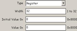
input ports (if any), and their output ports (if any). Pictured above is one part of the properties page for a simple register.
In More Depth: ALU
An ALU takes two inputs, and produces some output, according to the function output = input1 OP input2. Which operation it does is determined by the ‘Op’ input that it expects. For example, giving it an input of 0x02 will cause the two inputs to be multiplied, and the output port to be set to the result. To see what operations are available, how they are mapped to different Op fields, and to be able to change this information, right-click on the ALU itself and select “Edit ALU Ops”. Another notable output is ‘Z’ – it is a 1-bit line that is 1 when the output is equal to 0x00000000.
In Not-Much-More Depth: Constant Register
All this component does is always provide some “hardwired” value to the wire that connects to it. Nothing special to it, aside from the somewhat misleading name.
In More Depth: Halt
The halt component simply stops the execution when a certain condition (defined in its properties) on the wire connected to its input is met. Not useful for stepping.
In More Depth: Memory
The memory component represents a connection to memory (or, rather, caches) that we can access from within our processor. To load some useful things into memory initially, simply go to its properties and specify from which file the data must be loaded. These files have the extension “.smokmem”, and must be of a certain format. The format states that the first line must contain ‘@’ immediately followed by a number. This number states at which memory location to start laying down the following contents. Each line after the first is simply a hexadecimal (without the leading ‘0x’) representation of what that word in memory will contain. Note that only two components are able to interface with the memory component – the instruction fetch (IF), and the MemoryInterface.
In More Depth: PLA
The PLA component essentially maps some given input values to some predetermined output values. As we have discussed in class, this is very useful for implementing the control portion of our processor. To select an input port of the PLA component, simply right-click on it and select the appropriate option. When you try to connect some wire to the PLA output, you will be prompted with a question as to which output port you want. The behavior of the PLA is specified in a “.smokpla” file, that must be of a certain format. The PLA definition must be enclosed within “<smokplafile>” and “</smokplafile>” tags. One of the first lines, enclosed within “<decodetypes>” and “</decodetypes>” tags, specifies which instruction this is, by identifying the inputs. Any number of lines following this, enclosed by “<inputsignal>” and “</inputsignal>”, specify first the input port name, and then what value that input will have for a certain decode type. Then any number of lines specify the outputs. These lines are enclosed by “<outputsignal>” and “</outputsignal>”, and give first the output port name, and what value that output port will have for a given decode type. Values are binary strings, where the length of the string determines the width of the input/output port. ‘X’ represents the fact that that binary value does not matter in the given case.
Containers
You will notice that the workspace you get with SMOK is not all that big. One great way to avoid clutter, and also to promote object-orientedness, is to use containers. A container is simply some hardware, with some inputs and outputs, that is enclosed in a box. You can then use that box in your SMOK model, possibly even shrinking its size significantly to reduce the space that it uses. First of all, to create a component, open a new, blank SMOK model. There, place the hardware that you wish the container to have. Then define the inputs and outputs of the container by placing the PasserelleInput and PasserelleOutput components within this SMOK model. The input and output passerelles can be connected by wires to the hardware of the model. Once you are happy with the container, then right click on a blank portion of the workspace, and select “Save As Container”. This will create a “.smokcont” file that defines the container. Then, open the model where you want to use the container. Right-click on some blank space, select “Add Component”, and then pick the “Container” option (at the very bottom) of the following menu. Browse to your .smokcont file, and click OK. You will see that this container has been placed in your model, ready to do its job.
Once the container is in your model, you can resize it as
you want to. The input/output passerelles on the container act exactly like
input/output ports on any other component. If you want to get a closer look
inside some container, then double-click on blank space enclosed by the
container. Once you are done looking around, simply use the ![]() button to go to one higher level in the
container hierarchy (if you entered one container, it will take you back to
your processor).
button to go to one higher level in the
container hierarchy (if you entered one container, it will take you back to
your processor).
Processors Process, Don’t They?
So far, you have learned how to build a static model of our
processor. But now that all the components are down, and all the wires are
connected, what happens next? Well, you probably want to simulate the execution
of the processor you just made, just to test that it is correct. SMOK gives you
the option to do so. This is accomplished using the run toolbar (at the top
left of the SMOK window): ![]()
The first button is power-on – something that you do not need to worry about. The second button reinitializes the machine. In other words, it reloads all the .smokpla and .smokmem files, and resets all the components to their initial value states (in other words, everything that happens when you open your SMOKmodel file). The third button halts the execution of a running processor. The fourth button advances the clock by one cycle – that is, it steps one cycle in the processor. And the final button simply lets the processor run without restrictions. Remember that it will keep running and running and running unless you hit the stop button, or the halt component causes your machine to stop.
Other Good Things To Know
The SMOK documentation (on the SMOK homepage) is helpful in clearing up other oddness about how SMOK works. The component reference can come in very handy, too, as it describes what each component does for each different input value.
The running time of a SMOK model is discretized into clock cycles. At the very beginning of every clock cycle, data flows from registers, through the logic portion of its path, and then gets written when it sees a register in its path. For example, on a given clock cycle, our PC register might have some value. This value first propagates out along the output wire, goes through an adder, and then this new value would get written back to the PC register at the end of the given clock cycle. Most of the time, this is exactly what you would like to happen… but it also means that for our pipelined implementation the register files will need to become more complex.