
Extra-Credit Assignment UF: Applying UNION-FIND
Overview
This assignment is optional. Those who complete it successfully on time will earn 15 points of extra credit. If you do this assignment, do it as individual (not partnership) work.
In this assignment, we will be applying the UNION-FIND technique. It can be used for two different image-processing operations. One is determining and labeling the connected components of a spatial data structure. The other is segmenting the pixels of an image into regions ("segmentation"). This assignment involves implementing the first application, determining and labeling the connected components of an image.
Background
Connected Components of an Image
We define the strict pixel graph of an image to be the pair Gs = (V, E), where V is the set of pixels, like those shown above in the diagram for the previous exercise. Then E is the set of edges, where an edge e connects v0 = (x0, y0) with v1 = (x1, y1) provided | x0 - x1 | + | y0 - y1 | = 1 and the colors of the two pixels are equal. The strict pixel graph is undirected.
Consider the simple digital image below, in which each pixel's color is represented by just a single
letter. Here we can imagine Y = yellow, M = magenta, G = green.
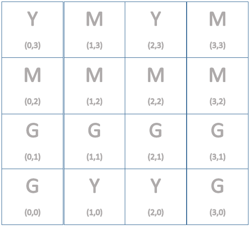
Exercise (not to be turned in). Draw the strict pixel graph on top of a copy of the image. The edges should be undirected.
Thought questions (not to be turned in): How many connected components are there in this graph? (A connected component C of a graph G is a subgraph of G that is connected within itself, and not connected to any vertices of G outside of C.) The number of connected components of an image is often used as an estimate of the number of separate objects or graphical elements in the image.
(not to be turned in) Number the connected components starting at 1. The components should be ordered according to the minimum pixelID value in them, where a pixelID for the pixel at (x,y) is y*w + x, where w is the width of the image in pixels (i.e., w is the number of columns in the image). The connected component containing the pixel at (0,0) should get number 1. Write a 1 on each pixel in that component. Find the next component by scanning the pixels in order of increasing pixelID values until you find a pixel that is not in a component already labeled. Label each pixel in this new component 2, etc., until you have labeled all the pixels of all the components. (By using pixelID values, we will be able to avoid the awkwardness of naming subsets using ordered pairs as we did in Q2a.)
Implementation of Connected Components Analysis
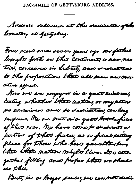
Using the main starter code and ProgressiveColors.java helper file, implement the features described below. The test image to use is a scan of the first page of Abraham Lincoln's Gettysburg Address, not only an appropriate reminder about Veterans Day, but a good example of a bicolor image having many connected components, each corresponding to a word of the document (although there are also some connected components that represent individual characters of text, and there are a number of separate connected components that represent parts of the background -- the paper on which Lincoln did his handwriting).
Finding the Connected Components of an Image.
Using a two-dimensional int array of pixelID values, named parentID, write code that applies the UNION-FIND method, as in the exercises above, to build a forest of up-trees for the current image. Each element of parentID will either be the pixelID value of the parent of the up-tree node, or -1 if the node itself is the root of an up-tree. Initially, before any of the UNION operations, each element of the array should be -1, since every pixel is in its own subset.
You should write a pair of methods getXcoord and getYcoord that will return the x and y coordinates of the pixel having a given pixelID value. Then it will be possible to follow the path from any pixel to the root of its up-tree by repeatedly getting the parent node's pixelID from the parentID array, and then from the pixelID getting the x and y coordinates of the parent, and then getting the its parent's pixelID, etc., until the root of the up-tree is reached. Implement the FIND method to perform that path following and return the pixelID of the root.
Your UNION method should take two pixelID values representing roots of up-trees, and it should make the one having the smaller pixelID value be the parent of the other.
Now apply your UNION-FIND implementation to the problem of analyzing an image. Your code will merge groups of pixels so that, at the end, each connected component of the strict pixel graph will be represented by one up-tree.
To do this, your code should scan the image considering all the pixel pairs for which edges exist (according to the definition of Gs, in Part I). Perform FIND_UNION on all such pairs. Starting at (x, y) = (0, 0), check to see if Gs contains an edge to (x+1, y) = (1, 0) and/or to (x, y+1) = (0, 1). If it does, perform the FIND operations on the endpoints of this edge, and if the results are different, then UNION the two subsets. After processing this pixel, go on to the next (incrementing x). When the first row of pixels is complete, do the same for the second row, etc., until all rows of pixels have been processed.
Instrument your UNION method, so that a count is maintained of the number of times UNION is called. That count should be set to zero before the scan begins. At the end, print out the count in the following style.
The number of times that the method UNION was called for this image is: 2764.
Counting the Connected Components
Next, set an integer variable, count, to zero, and do another scan of the parentID array. Each time a root of an uptree is encountered, increment count. At the end of the scan print out the value of count with explanatory text as follows:
The number of connected components in this image is: 79.
Note that the number of times UNION was called, plus the number of connected components found should add up to the number of pixels in the image, so you can use this fact in debugging your code.
Labeling the Connected Components
Now modify your code (that does the scanning and counting above) so that each time an uptree root is encountered, not only is the count incremented, but that root is associated with the count in a hashtable named componentNumber. Thus the keys of your hashtable will be of class Integer (representing the roots' pixelID values), and the values will also be of class Integer (representing the counts -- i.e., the connected component numbers).
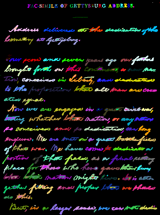
Write code for another scan of the image, this time doing the following for each pixel: (a) FINDing the root of the pixel's up-tree; (b) Looking up the count value for that root in the hashtable. (Then convert the Integer to an int.) Let's call the resulting int k. (c) Determine the kth progressive color by calling the provided method getProgressiveColor(k). (d) Replace the rgb information of biWorking with the new color.
When the scan is complete, the method repaint() should be called to show the newly colored image.
Here is what your image should look like, after you have completed the labeling for the
given image of page 1 of Lincoln's Gettysburg Address. The colors may
depend on your scanning order and how you implement the UNION operation. However, we would
expect the image to look like this, assuming you are following the specifications given above.
(Thanks to CSE graduate student Johnson Goh for providing this example.)
Turn in your source files and your recolored Gettysburg Address image through our Catalyst CollectIt dropbox. due Wednesday, Nov. 23 at 11:59 PM.
Version 1.0. Last updated Oct. 31, 2016, at 1:35 PM.