LabsLand Joystick Tutorial
Introduction
This tutorial provides a method for using a green, 360-degree virtual joystick input on LabsLand.
Web Interface
You must select the "Full experience with Joystick" user interface, which also includes VGA output and audio input/output. The "Configure" button will allow you to upload audio files if you intend to use the audio features of this interface.
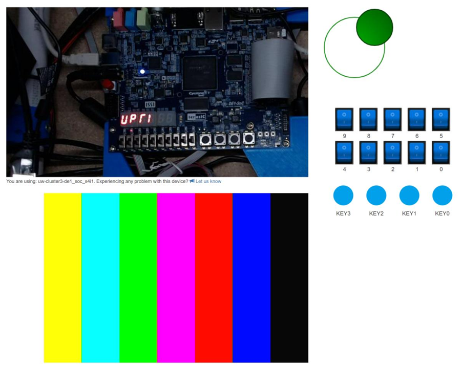
The joystick is manipulated by clicking the solid green circle and then dragging your mouse in the direction that you want it to go. In the image above, the joystick is currently being dragged to the far upper-right.
Using the Joystick
Provided code
- serial_driver.sv — A generic serial driver for communicating with the LabsLand FPGA management system (a Raspberry Pico).
-
joystick_driver.sv — The driver that converts the
serialized data from
serial_driverto the joystick interface (i.e., x- and y-position of the joystick). -
joystick_example.sv — Example code that uses
joystick_driverto read the position inputs and then shows the current quadrant (up-left, up-right, down-left, down-right) on the DE1-SoC outputs. Intended to be a starting point for your own project.
Driver Ports
input clk,
input data_in, // connect to V_GPIO[28]
output reg latch, // connect to V_GPIO[26]
output reg pulse, // connect to V_GPIO[27]
output reg [7:0] positionX,
output reg [7:0] positionY
);
The positions are represented as 8-bit numbers in Two's Complement
signed notation (which can represent the values -128 to +127),
though note that the type reg is unsigned
by default.
Other Inputs Alongside the Joystick
You are able to still use KEYs and SWs when using the joystick, but they will require some changes to your
top-level module code. There are two different ways you can do it:
Method 1: Use the V_GPIO equivalents
V_GPIO[5]is equivalent toSW[0]V_GPIO[6]is equivalent toSW[1]- ⋮ ⋮
V_GPIO[14]is equivalent toSW[9]
Method 2: Shorten the bus width for V_GPIO
Change inout [35:0] V_GPIO to be inout [35:23] V_GPIO.
From there, you can add in SW and KEY into your top-level
module inputs list as normal.
Tutorial developed by Justin Hsia and Matt Guo. Code supplied by LabsLand.