HW4: Algorithmic State Machines with Datapath
Out: Thursday, April 23, 2026
Due: Monday, May 4, 2026 by 11:59 PM
Closes: Tuesday, May 5, 2026 by 11:59 PM
Homework Files
For .v files, you may want to right-click and save/download instead of clicking.
Problems
Problem 1
We want to build a digital system that counts the number of people in
a room.
The one door through which people enter the room has a photocell that
changes a signal x from 1 to 0
while the light is interrupted.
People leave the room from a second door with a similar photocell
that changes a signal y from 1 to
0 while the light is interrupted.
The datapath circuit consists of an up-down counter with a
display that shows how many people are in the room.
Only one person can pass through each door at a time and each person
should only be counted once.
- Construct a block diagram and an ASMD chart for this system.
Hint: You should use 4 states corresponding with each combination of the sensors' outputsxandy.
Problem 2
In this problem, we will investigate the implied timing of ASMD charts. Recall that any datapath effects from the active path take effect when you EXIT the state.
Our goal is implement a rudimentary search algorithm on a ROM, whose
datapath is shown below.
We want to cycle through the addresses (adding 1 each time) until a
specified number N is found.
We output a status indicator found as well as the
first encountered address A in which it was found.
For this purposes of this problem, you should ignore the situation
where N is not in the ROM.
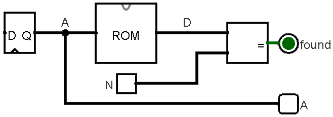
A is the output of a register/counter and represents
the address we're currently checking.
D is the output of the ROM that is compared against
a specified number N.
In the questions below, when asked, draw a partial ASMD
chart for just the searching part of the algorithm (i.e.,
you don't need to show the idling, initialization, or done states and
you can leave paths that go to or come from these states "hanging").
Use incr_A as a control signal and found as
a status signal.
Your goal is to complete the task in as few clock cycles as
possible.
- The ROM is a purely combinational circuit.
Draw out the partial ASMD chart using the ROM as-is.
If
Nis found on the 4th searched address, how many clock cycles does the searching portion of the algorithm consume? - We now synchronize the output of the ROM by
registering it.
Draw out the partial ASMD chart using the registered ROM output.
If
Nis found on the 4th searched address, how many clock cycles does the searching portion of the algorithm consume?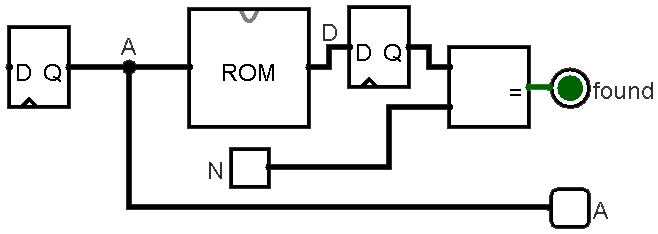
Figure 2: Updated datapath with registered ROM output. - Harry the Husky claims that we can save clock
cycles with the registered ROM output if we also register the
Aoutput. Draw out the partial ASMD chart using the synchronizedAoutput, remembering that we want theAoutput to reflect the correct address when the searching is done. You may use an additional control signaldecr_Afor this ASMD. IfNis found on the 4th searched address, how many clock cycles does the searching portion of the algorithm consume?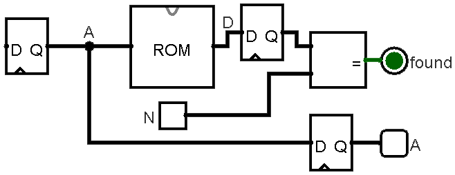
Figure 3: Updated datapath with synchronized Aoutput.
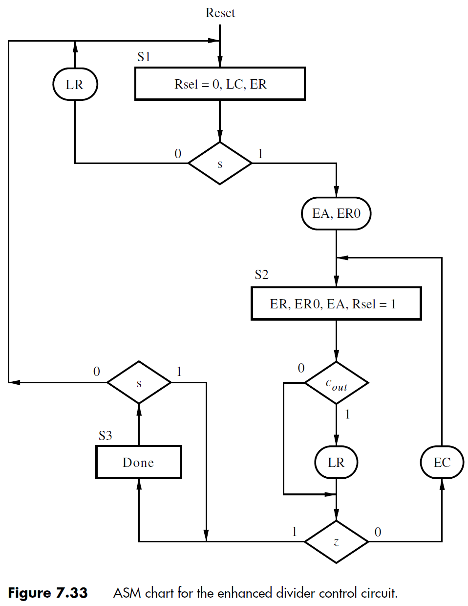
Problem 3
You are provided a buggy Verilog implementation of a divider circuit similar to the one discussed in lecture in the files: divider.v, downcount.v, muxdff.v, regne.v, and shiftlne.v (files).
- Create a test bench (divider_tb.sv) and use it to update
the provided code to work as intended.
Make sure that your code fixes are documented in code comments for
each file.
- All Verilog code works in SystemVerilog if you would like to update to .sv files.
- You are allowed to parameterize modules, but you are NOT allowed to change any of the module port lists (i.e., number of ports, ordering, names).
- Include screenshots of any warnings, errors, or simulation results of the original code and point out the parts that helped you identify the faulty behavior that you found.
|
Signal naming scheme:
|
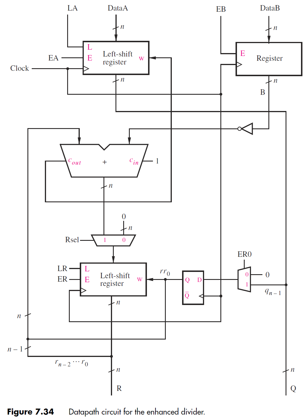
|
Component naming scheme:
The output signals at the bottom are the quotient (Q) and remainder (R). The down-counter (C) is not shown but used to generate the z signal. |
Submission Requirements
Due by the end of the deadline day, submit your solutions (e.g., text, diagrams, screenshots, work) as a single PDF file ending in .pdf (all lowercase) to Gradescope.
- Include the requirements listed in the Assignment Requirements.
- At the end of your document, estimate how long you
spent working on the homework and rate the difficulty on the
following scale:
Very Hard — Hard — Moderate — Easy — Very Easy - As separate files, upload your commented
(System)Verilog files, including test benches.
- divider.(s)v
- downcount.(s)v
- muxdff.(s)v
- regne.(s)v
- shiftlne.(s)v
- divider_tb.sv (new!)
Grading Rubric
- Block diagram
- ASMD chart
- 3 partial ASMD charts
- Number of clock cycles for each part (3 total)
- Fixes made to code (autograded) and documented
- Simulation results for original and fixed behaviors
- Code style