Lab 5: Display Interface
Overview
In this lab, we will learn how to display images on a VGA terminal using the DE1-SoC's video-out port and implement a line-drawing algorithm.
The Pixel Buffer
The DE1-SoC includes a video-out port with a VGA controller that can be connected to a standard VGA monitor. The VGA controller supports a screen resolution of 640 × 480. The image that is displayed by the VGA controller is derived from two sources: a pixel buffer and a character buffer, however, we will only discuss and use the pixel buffer in this lab.
The pixel buffer for the video-out port holds the data (color) for each pixel that is displayed by the VGA controller, with the coordinate (0,0) referring to the top-left corner of the image (Figure 1).
|
|
|
The color of a pixel is represented within a 16-bit halfword, with five bits for the red and blue components and six bits for the green component (Figure 2a). The address of an individual pixel in the pixel buffer is given by the sum of a base address and an (x,y) offset (represented as seen in Figure 2b).
In the DE1-SoC, the default base address of the pixel buffer is 0xC8000000, which corresponds to the starting address of the FPGA on-chip memory.
| e.g., | pixel (0,0) has address | 0xC8000000 + 0b0…0 00000000 000000000 0 = 0xC8000000. | ||
| pixel (1,0) has address | 0xC8000000 + 0b0…0 00000000 000000001 0 = 0xC8000002. | |||
| pixel (0,1) has address | 0xC8000000 + 0b0…0 00000001 000000000 0 = 0xC8000400. | |||
| pixel (319,239)'s addr | 0xC8000000 + 0b0…0 11101111 100111111 0 = 0xC803BE7E. |
You can create an image by writing color values into the pixel addresses as described above. A dedicated pixel buffer controller reads this pixel data from the memory and sends it to the VGA display. The controller reads the pixel data in sequential address order, starting with the pixel data corresponding to the upper-left corner of the VGA screen and proceeding horizontally, then vertically until it reaches the data for the lower-right corner; this process repeats continuously. You can modify the pixel data at any time by writing to the pixel addresses. Writes to the pixel buffer are automatically interleaved in the hardware with the read operations that are performed by the pixel buffer controller.
It is also possible to prepare a new image for the VGA display without changing the content of the pixel buffer using the concept of double-buffering. In this scheme, you switch between two pixel buffers, front and back, one of which is being sent to the VGA while the other is used to prepare the next frame. You don't need to worry about double-buffering for this lab, but may find it helpful in Lab 6.
Bresenham's Line Drawing Algorithm
Drawing a line on a screen requires coloring pixels between two points (x1,y1) and (x2,y2), such that the pixels represent the desired line as closely as possible. For example, if we want to draw a line between points (1,1) and (12,5), we cannot draw the line precisely – we can only draw a shape that is similar to the line by coloring the pixels that fall closest to the line's ideal location on the screen. This is illustrated in Figure 3, where the squares represent pixels on the screen.
We can use algebra to determine which pixels to color based on the slope and end points of the line. The slope of our example line is (y2-y1)/(x2-x1)=4/11. Starting at one endpoint (1,1), we move along the x-axis to the other endpoint and compute the y-position for each x-position as: y=y1+slope*(x-x1).
Thus, for x=2, which you can think of as a column of pixels, the y-position of the pixel for the line is 1+(4/11)*(2-1)=15/11. Since pixel locations are defined by integer values, we round this result to the nearest integer, and determine that we should color the pixel at (2,1). For x=3, we compute y=19/11 and color the pixel at (3,2). Similarly, we compute pixels to color through x=12=x2.
This approach (compute a y-position for every x-position) has drawbacks when a line is steep (i.e., |slope|>1), since it will span more rows than it does columns. In this case, our calculations will not produce a smooth-looking line and will not work at all for a vertical line. To address this problem, we can alter the algorithm to instead move along the y-axis when a line is steep. With this change, we can implement what is known as Bresenham's line algorithm; two different pseudocodes are given in Figure 4 and the first link below – either will work for this lab.
If you would like to learn more about how Bresenham's line algorithm works:
- http://members.chello.at/easyfilter/bresenham.html
- https://en.wikipedia.org/wiki/Bresenham%27s_line_algorithm
 1 draw_line(x0, x1, y0, y1):
 2
 3   boolean is_steep = abs(y1-y0) > abs(x1-x0)
 4   if is_steep then
 5     swap(x0, y0)
 6     swap(x1, y1)
 7   if x0 > x1 then
 8     swap(x0, x1)
 9     swap(y0, y1)
10
11   int deltax = x1-x0
12   int deltay = abs(y1-y0)
13   int error = -(deltax/2)
14   int y = y0
15   if y0 < y1 then y_step = 1 else y_step = -1
16
17   for x from x0 to x1
18     if is_steep then draw_pixel(y,x) else draw_pixel(x,y)
19     error = error + deltay
20     if error >= 0 then
21       y = y + y_step
22       error = error − deltax
The first 15 lines of the algorithm make the needed adjustments
depending on whether or not the line is steep.
Lines 17 to 22 then increment the x variable one step at
a time and computes the corresponding y-value.
The y-value is incremented when needed to stay as close to
the ideal location of the line as possible.
Bresenham's line algorithm calculates an error variable
to decide whether or not to increment each y-value.
The version of the algorithm shown in Figure 4 uses only integers.
Instructions
Task 1 – VGA Connection (no deliverables)
- Download lab5_startercode.zip (code).
- Unzip the Quartus project folder, which contains
some files that will help you work with the VGA output of the
DE1-SoC.
In particular, there are three SystemVerilog files:
- VGA_framebuffer.sv is a driver for the VGA port of the board. You don't need to edit or understand this file, but you might notice that it uses a 38,400-byte framebuffer register, similar to what was described above. The ternary operator on the last line of this file controls the colors of the lines you'll be drawing (only black or white for this lab).
- line_drawer.sv is a skeleton file for you to implement Bresenham's line algorithm.
- DE1_SoC.sv is a top-level module that instantiates both of the above modules. This should compile and function as-is, but you will modify it for later tasks.
- Verify that the project compiles on LabsLand
and produces an output on your monitor.
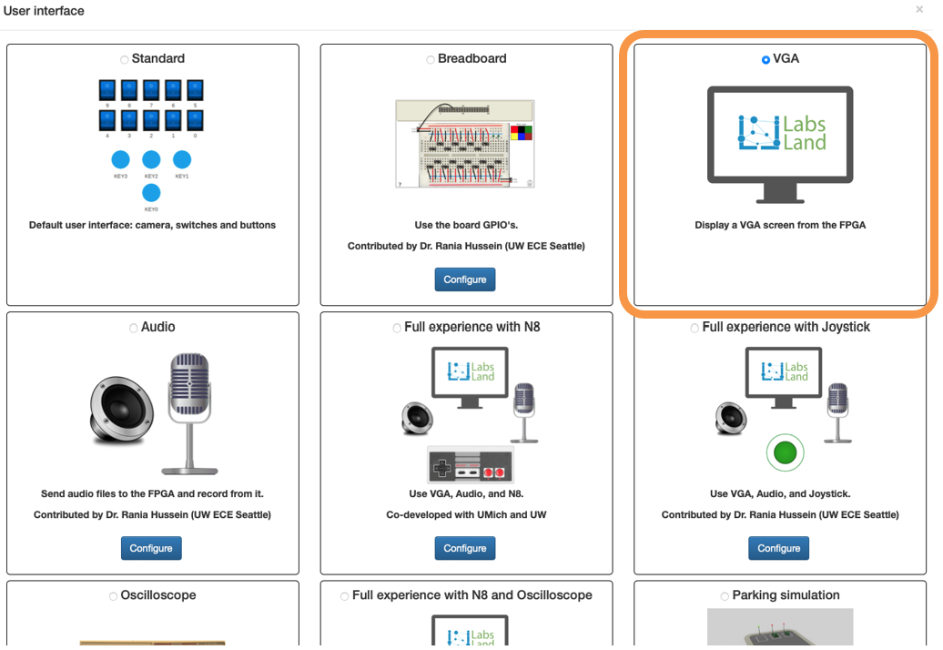
- On LabsLand, choose the "VGA" option for the interface (shown in Figure 5).
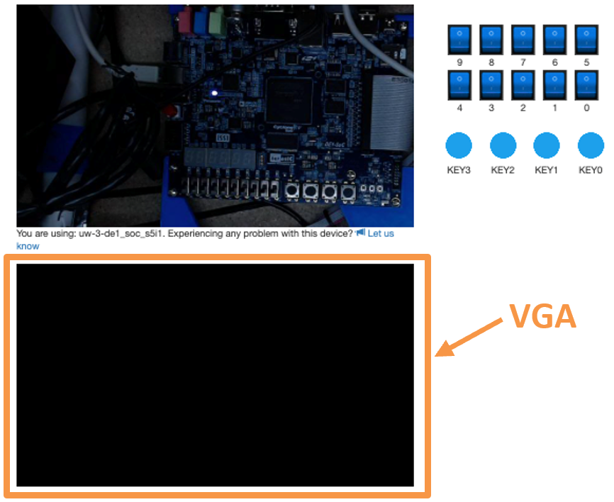
- Once the code is synthesized and uploaded onto an FPGA, the VGA monitor will initially produce a rainbow gradient before turning black (shown in Figure 6).
|
|
Task 2 – Implement the Line-Drawing Algorithm
Some notes about the line_drawer.sv:
- It takes inputs
x0,y0,x1,y1, corresponding to the coordinate pairs (x0,y0) and (x1,y1). - On positive edges of the input clock
clk, the outputsxandyform a coordinate pair on the line between (x0,y0) and (x1,y1). On any given clock cycle,xandyshould each change by at most one pixel, since we're guaranteed to use |slope|≤1. - As indicated in the file, you'll need to create
some local registers (i.e.,
logicvariables) to keep track of things. Notice that the example signalerroris declared assignedand is a bit longer than the coordinate ports.
Your task is to draw a line between any two arbitrary points on the monitor. However, Bresenham's line algorithm can get complicated and you need to handle drawing to the left, right, up, or down, and both steep and gradual lines. Instead of doing this all at once, you'll probably want to work in smaller steps. The following are suggestions on how to approach this problem, but you can complete this task in whatever way makes the most sense to you:
- Set
y0 = y1 > 0(in case of monitor cut-off) and use line_drawer.sv to draw horizontal lines – i.e., implement the for-loop mechanics andx0 > x1conditional. - Modify your algorithm to handle perfectly diagonal
lines from any arbitrary starting point – i.e., handle
y_step. - Modify your algorithm to handle lines with gradual
slopes, e.g., from (0,0) to (100,20) –
i.e., handle
deltax,deltay, anderror. - Modify your algorithm to handle lines with steep
slopes, e.g., from (0,0) to (20,100) –
i.e., handle
is_steep.
While you won't be demoing this task, you will need to include simulation results for drawing left-up, right-up, left-down, and right-down for both steep and gradual slopes (8 total).
Task 3 – Animate an Object
Modify DE1_SoC.sv to implement the following:
- Use your line algorithm to draw a line on the monitor and
"animate" it to move around the screen.
- You can be as creative as you want with this animation, but make sure that it demonstrates the full functionality of your line-drawing algorithm. You should draw lines to the left and right with negative, positive, steep and shallow slopes as well as horizontal and vertical lines.
- Implement a reset that, when activated, clears the
screen by drawing every pixel to be black.
- You'll need to modify the
pixel_colorport connection to theVGA_framebuffermodule to choose between drawing black or white.
- You'll need to modify the
Note that you don't need to provide simulation results for your animation, but instead will include a drawing or image of what it produces.
Lab Requirements
Lab Report
Due by the end of Friday, submitted as a PDF on .
- Include the required Design Procedure, Results, and
Experience Report sections along with the other requirements
listed in the
.
- Task 1 has no deliverables.
- Task 2 requires 8 different simulations.
- Task 3 does not require any simulation but does need a drawing or image.
- As separate files, upload your commented code files (.sv), including test benches.
Lab Demo
Due within one week of the lab report deadline, but typically during your assigned demo slot or a scheduled office hour.
- Explain your
line_drawermodule code to the TA. - Demonstrate your working Task 3 that animates an object moving around the screen.
- Demonstrate your working Task 3 reset that clears the monitor.
- Be prepared to answer 1-2 questions about your lab experience to the TA.
Grading Rubric
- A diagram (e.g., ASMD chart) must be included for your line_drawer algorithm.
- The design of your animation algorithm must be described and please include a diagram, if appropriate.
- Correct behavior must be shown for drawing left-up, right-up, left-down, right-down for both steep and gradual slopes.
- Include a drawing or image of your final animation.
- Bonus points available for particularly impressive animations.
(10 pts)