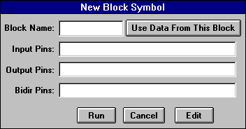
We will turn our "simple" design containing a single AND gate into a block to be used in future designs. In this case, of course, this is sort of silly as it only contains an AND gate. However, we could have had an arbitrarily large schematic and would now encapsulate it all in a symbol we can use in other schematics. This is how we can build up hierarchical schematic diagrams using Synario. To create a new symbol, we need to go back into the schematics editor. There are many ways to do this. A simple way is to just double-click on the "simple" schematic "Source" in the project navigator. Once the schematic editor window is open, we can select "New Block Symbol" from the "Add" menu of the schematic editor. The following dialog box pops-up.

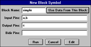
For now, we can simply press the "Use Data From This Block" button since we want to create a new symbol with the same inputs and outputs as the schematic diagram with our AND gate. This yields the following:

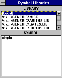
One very important thing to keep in mind is that the block name must match the name of the lower level source i.e for Schematics, it is the file name;for ABEL-HDL, it is the module name. Hence in our case since we named the file "simple.sch", we will give the block name as "simple". Once we create our new symbol it will be added to a local library that we can now see in the "Symbol Libraries" palette that we can cause to pop-up through the "Symbol" entry in the "Add" menu.

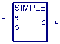
We can now close this schematic. When we are ready to use our new symbol in a new schematic, we can get to it in this manner. It will appear in the schematic as the following:

The symbol will be stored in the same directory as the schematic from which it was defined. That means we should use the same directory for any designs that will require this symbol.