Let's create the three-bit counter in ABEL. The completed project is called "counter.syn". Let's look at the ABEL source file first. It is going to take three inputs--EN will enable the counter. When it is zero the counter stops. RST will allow us to reset the counter whenever it's value is one. And finally there is in input labeled 'clk' which will hook to the individual flip-flops clock inputs.
You'll notice a few differences from what we have seen in the past. Notice how the outputs A, B, and C are labeled "pin istype 'reg, buffer'". This is telling Synario that we are going to be using flip-flops. Next, look at the aliases used. "current_count" is set to [A.fb, B.fb, C.fb]. This is because the value of the flip-flop is available through .fb (for feedback). There are also aliases S0 through S7 representing eight unique "states" that this machine can be in, each respectively representing the binary number the counter represents. Finally, notice how you can also write comments like C++
Now, in the EQUATIONS section, notice how each flip-flop's clk input is assigned. Without this, they would never accept new values because they rely on the clock. RST allows us to reset the value of the flip-flops to zero whenever this signal is enabled. Lastly in the EQUATIONS section you see eight WHEN-THEN statements. These compare current_count to the eight unique states, and then assigns the appropriate values to the flip-flops for the next state. So, if the flip-flops currently hold the binary representation of zero, on the next clock cycle they will be assigned the value represented by S1, namely the representation of 'one', and so on. Also notice
Now, let's look at the Verilog Test Fixture.
Here we see something new--multiple initial begin's and a 'forever begin' statement. We can have multiple initial begins. For example, we start with an initial begin to set the clk's initial value with zero. We can then nest another loop inside this. With the forever begin we are declaring a timing loop that confinues 'forever'. As you can see, every five time units the clock will go to 'one' (high), let five more time units pass and then go back to 'zero' (low). We then end both the forever begin and the first initial begin.
Next, we start another initial begin. It is important to understand that, while this is a seperate initial begin, it runs in parallel with the other loops. This can really cause problems if we are not careful. We need to pay close attention to ensure we are not changing inputs too close to the clock edge. For this reason, you can see that the 'EN' and 'RST' values are changed well before the clock edges. Had there been other inputs whose values we wish to vary, we would also change them at the same point with respect to the clk. A good suggestion here is to change inputs halfway between clock transitions.
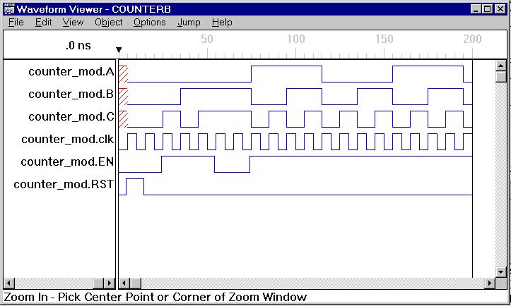
Now lets look at the resulting waveforms on the viewer.
Notice how the clock continues from high to low throughout the entire test. You can also verify that the counter is working correctly. Another thing to notice is how the value of the flip-flops do not change until a clock edge. Look at RST. Even though it goes high at 3ns, it isn't until the clock goes high at 5ns that the values in the flip-flops are set. Also, once RST has gone low and EN has gone high, it is not until a clock edge that the counter acutually begins counting. Remember, the value of the flip-flops do not change until there is a clock edge.