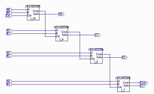
Here we would give an example of how to create a hierarchical design using just the schematic. Before going through this example you should familiarize yourself with the section on how to create the block symbols in the schematic editor.
Our goal here is to create a four-bit adder using full adder block as a new symbol. The full adder block is basically a schematic for a full adder with inputs A, B, Cin and outputs S and Cout.
To implement the four-bit adder we will follow these steps :
Following the steps indicated in Tutorial 1 : Creating a Schematic we create the following schematic for the full adder with inputs A, B, Cin and outputs S and Cout :

Following the steps indicated in Tutorial 1 : Creating a block symbol we create the following full adder block symbol:

Once again following the steps for creating the schematic we arrive at the following schematic for the four-bit adder:

The above schematic represents the hierarchical design for the 4-bit adder using only the full adder block symbols.