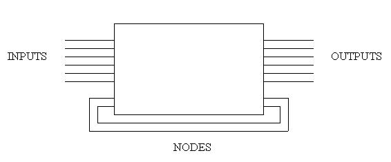
A node is basically an output whose value is never passed, but only used internally within a module. Like outputs, nodes can be declared to be either combinational or registered. Nodes are implemented in ABEL-HDL. A block diagram of a module that used nodes would look as follows:
1. For representing the state bits of an FSM. In FSMs, state bits are generally represented as nodes since usually only the FSM itself cares about its state. Using nodes, an FSM can compute the value of its state bits as if the bits were normal outputs, yet by using nodes the FSM is not forced to pass unnecessary data to other modules or waste output pins on bits only used internally.
2. For acting as the hardware equivalents of software's intermediate variables. It is general knowledge that one long equation is harder for a person to read and understand than several shorter ones, but PLDs give us an even better reason to break down long equations: each output pins has a limited number of product terms that can be used to compute its value. When a design is mapped to a PLD, Synario attempts to "fit" the design by breaking down any equations that are composed of more product terms than the given PLD supports, but it is also general knowledge that computers are not very bright, hence there are times when one might need to break down a long equation oneself in order to get one's design to map. For example, consider the following equation:
output = (term1 & term2) # (term2 & term3) # (term3 & term4) # (term4 & term5) # (term5 & term6) # (term6 & term7) #
         (term 7 & term8) # (term 8 & term9) # (term9 & term1);
If we were trying to map a design which used this equation to the EO320PLD, which only supports a maximum of 8 product terms per output pin, the equation would have to be broken down before the design would fit. We could break it down ourselves by doing the following:
intermediateTerm1 = (term1 & term2) # (term2 & term3) # (term3 & term4) # (term4 & term5);
intermediateTerm2 = (term5 & term6) # (term6 & term7) # (term 7 & term8) # (term 8 & term9) # (term9 & term1);

output = intermediateTerm1 & intermeditateTerm2;
These equations would be logically equivalent to the first long equation but fits under the EO320's restriction of 8 product terms per output pin.
3. For representing identical multi-pin used in several different equations. We all know that repetitve code is bad; it is always preferrable to isolate identical code in one location whenever possible so that making a change later only requires changing one section of your code rather than having to look all over trying to find all places you used the identical code. For example, consider the following equations:
someTerm2 = (a # b # c) & cin2;
someTerm1 = (a # b # c) & cin1;
someTerm0 = (a # b # c) & cin0;
A much better alternative to this would be to use a node to encapsulate the shared term (a # b # c). This would eliminate the repetitve code by isolating it in one location:
sharedTerm = a # b # c;

someTerm2 = sharedTerm & cin2;
someTerm1 = sharedTerm & cin1;
someTerm0 = sharedTerm & cin0;
Now if our specification were to change so that someTerm2..someTerm0 were based on an additional input, "d", we would simply have make the following alteration to the equation of our shared term:
sharedTerm = a # b # c # d;
Nodes are declared in the same general location of an ABEL-HDL source as are inputs and outputs. The syntax for their instantiation looks as follows:
combinationalNode       NODE ISTYPE 'COM';
registeredNode          NODE ISTYPE 'REG,BUFFER';
Note that the "NODE" keyword is all that differentiates a node from an output ("PIN"). In addition, nodes are NOT included in the "INTERFACE" statement. These are the only two differences between implementing nodes vs. implementing outputs; nodes may be treated in every other respect as if they were outputs. This means that not only are they assigned to in the same fashion, but also that several nodes and outputs could be wrapped together under one alias name if such were ever desired.
INTERFACE (clk,rst -> out1);

clk                     PIN;
rst                     PIN;

out1                    PIN ISTYPE 'COM';

stateBit3..stateBit0    NODE ISTYPE 'REG,BUFFER';

machineState = [stateBit3..stateBit0];

STATE_DIAGRAM machineState

STATE 0:        GOTO 3;
STATE 1:        GOTO 0 WITH
                        {
                        out1 = 1;
                        }
STATE 2:        GOTO 1;
                        {
                        out1 = 0;
                        }
STATE 3:        GOTO 2;

EQUATIONS

machineState.clk = clk;
machineState.clr = rst;

WHEN (machineState > 3) THEN
        {
        machineState := 0;
        }