CSE 370 Introductory Laboratory Assignment

Simon


Assigned: Monday, November 16, 2009
Due: Beginning of next Lab Section


Objective

The objective of this lab is to use a finite state machine to implement the controller logic for the game of Simon. The game consists of echoing a sequence of flashing LEDs using the buttons on your board. Initially the sequence consists of a single LED followed by a single button press. Every time you successfully mimic the sequence, the sequence elongates by one. If you haven't played the game before or it has been awhile, take a moment to try it out: Flash Simon.

Tasks

  1. Download this archived workspace: Lab7.zip and unarchive it by doing the following:
    1. Open the workspace you wish to use for this project using Active HDL.
    2. Go to Design->Restore Design
    3. For "Archive Path" browse to where you saved the file.
    4. For "Restore To" browse to the folder containing your workspace.
    5. Click "Start". Active will extract the file. Now click "Close".
    6. Go to Workspace->Add Existing Design to Workspace
    7. Go to where you restored the design and open Lab7.adf in the Lab7 folder.
    8. If you are adding this Design to a Workspace containing other designs be sure to right-click the Design and 'Set As Active Design'.
    9. Use 'Compile All' to link all the provided Verilog modules into the Design's library. Now you should be able to open the provided Block Diagram and view each module's implementation by double-clicking the respective blocks.

  2. Read the below specification for the game of Simon and create a state machine for the controller module (all the other modules have been provided). Be sure to uncomment the controller module before you begin! Call-over your TA to check-off your state machine diagram when you're ready to begin coding.
  3. Implement the controller to create a working game of Simon based-on the control flow of the below pseudocode. If you've forgotten how to describe state machines using Verilog, refer to the FSM Tutorial from last week's lab.

Specification

  1. Flipping the reset switch (SW0) down will initiate a new game. Toggling the reset switch up and then down should begin a new game regardless of what state the current game is in.
  2. A game is comprised of a set of rounds. The game continues until ten rounds have been played (a player win) or the player makes a mistake (a player loss).
  3. Each round consists of the sequence playback followed by the player's attempt to mimic the sequence.
  4. For sequence playback, each of the sequence's flashed LED pairs should be separated by a small delay during which the green LEDs are off. A good ordering for this would be: delay, LED pair 1, delay, LED pair 2, ... delay, LED pair N. Note that you are also delaying while each LED pair is being displayed (if you only flashed them for a single clock cycle they would not be visible). The time that the LEDs are on should be longer than the delay between them.
  5. Each of the player's attempts to mimic the sequence should display the LED pair which corresponds to the correct button for that element of the sequence, regardless of whether or not the player pushed the correct button. This LED pair should remain illuminated until the player releases the button. If the wrong button was pressed the hex display will show the word "lose". If the player mimics the entire sequence without a mistake then the game should continue to the next round or, if the current round is the last round, then notify the player of his/her victory by showing "good" on the hex display.


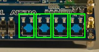
    The correspondence between buttons and LED pairs

  6. Once the player wins or loses the game should not accept any more input until it is reset.
  7. The red LEDs should display a tally of the rounds completed. For instance, at the beginning of a new game no red LEDs should be illuminated. After the player wins all ten red LEDs should be illuminated.
Here is a complete working implementation for comparison. Yours should behave like this except the middle segment of HEX3 should not be on during gameplay.

Where to start

The design you've been given contains the modules to illuminate the LEDs, generate the sequence, keep track of rounds, generate delays, etc. Your task is to implement the controller for all these modules. Without the controller these modules will sit idly. The controller's output signals signal these modules what to do. The controller's inputs provide it with information about the current game.
To better understand what this controller has to do let's first look at some pseudocode for how you might write a program to implement this logic:
	int[] sequence = generate_sequence();
	for (int round = 0; round < 10; round++) {
		for (int position = 0; position <= round; position++) {
			short pause
			show green LED pair for sequence[position]
			long pause
			turn off green LED pair
		}
		for (int position = 0; position <= round; position++) {
			while a button is not pressed {
				do nothing
			}
			show green LED pair for sequence[position]
			if the wrong button was pressed {
				display "lose"
				while a button is still pressed {
					display green LED pair
				}
				turn off green LED pair
				while (true) {
					continue to display "lose"
				}
			} else {
				while a button is still pressed {
					display green LED pair
				}
				turn off green LED pair
			}
		}
	}
	while true {
	      display "win"
        }
        
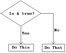
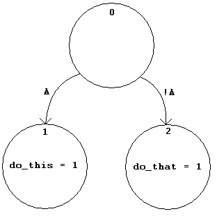
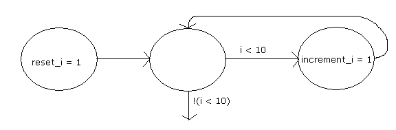
However, this is a hardware class. So why look at this program? Well, a flow chart of this program's execution (its control flow) can be converted into a finite state machine! Let's see how this works by examining the conversion of both 'if' and 'for' statements. Note that in a state machine you cannot call a function but you can output signals that cause things to happen in other modules.

Procedural Code Flow Chart State Diagram


if (a) {
	do_this();
} else {
	do_that();
}


for(i=0; i < 10; i++);
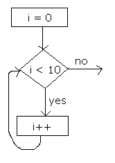
			

Lab Demonstration/Turn-In Requirements

  1. Have a TA visually inspect a diagram of the FSM you plan to implement for the game's controller logic.
  2. Demonstrate your Simon prowess and working implementation to your TA
    (Debugging Tip: Not performing an initial reset leaves the provided pseudo-random number generator unseeded, therefore the sequence will consist of the same LED pair throughout the game).

Comments to: cse370-webmaster@cs.washington.edu