CSE370 Laboratory Assignment 3
Programming in Verilog and Test Fixtures
Distributed: Friday, April
6, 2007
Due: By the end of lab session
Objectives
In this laboratory assignment you will continue to learn how
to use the Aldec Active-HDL tool. This time the focus will be on how to create
Verilog modules. You will also see how Verilog modules can be used as
test fixtures to help you verify your circuit. By the end of this lab you
should feel comfortable creating a Verilog module directly and setting up a
test fixture.
*Save all the files that you create in this lab. We will use them later.
Tasks
1. Complete
the Active-HDL Tutorial #3, which
describes how to write simple Verilog modules and use them in schematics. Take a look at
Part 1 of Tutorial
#2, which describes how to use a test fixture. As part of the tutorial, you will write and
test the Verilog module for a full-adder. Create a test schematic by using
this test fixture (right click and click "save as" if download doesn't start automatically). Test fixtures will be covered in more
detail next week, so don't worry about how they work for now. Make
sure that your Verilog module works correctly. Once you have imported
FA_tf and compiled it, hook it up like this:
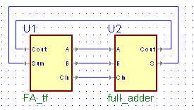
At this point we need to simulate it. There is
no need to create a waveform for simulation as you did last week. First compile your test diagram, which
includes your connected full adder verilog module and the test fixture as shown in the picture above. Then initialize
the simulation after setting it top level and finally click run. It will stop automatically when it is done.
Your console should show that the test passed successfully (or it will give you an error).
2. Complete Part 2 of Tutorial #2, which describes how to use buses and bus input and output terminals. In this part, you will create a four-bit full adder by using one-bit full adders that you created in previous part. Create a test schematic for your four-bit full adder by using this test fixture. Attention: In the tutorial, four-bit full adder is created by using lib370 gates (pink gates). However, since we will be synthesizing this into a PAL later in the quarter, you should use built-in symbols (yellow gates). You will see built-in symbols in the symbols toolbox located on the right. Make sure that you don't have any lib370 gates in your block diagram, otherwise it won't synthesize.
3. Create
a Verilog module in Active-HDL to detect a Fibonacci number between 1 and
15 (1, 2, 3, 5, 8, 13). Test it with this test
fixture. NOTE: In step 3 you will wire up your Fibonacci
circuit, so it is suggested that you come up with a boolean expression that uses
NANDs and/or NORs as opposed to if-than-elses or other constructs. This
way once your circuit passes simulation, it will be easier to move from the
verilog to the gates on your board and you will know that your logic is
correct. Show a TA your equation before proceeding.
HINT: As you learned in class, don't cares can be usefull in
simplifying a circuit. If you wish you may treat 0 as a don't care,
inform the TA as to your design decision when they check you off.
4. Using your logic from task 2, construct your circuit that will identify a "Fibonacci Number" on the prototyping board by connecting the inputs to switches and the output to an LED. You will need 4 switches and 1 LED for this part. Please use: SW1 through SW4 for number value, and LED1 for the result. Here are the chip maps. Demonstrate your circuit to a TA and have them check you off as having completed this laboratory assignment. They may ask you to show them your work and explain your circuit. HINT: If you circuit is not working as expected use the logic probe to trace through the circuit from this inputs to the output, checking the observed logic at each step, to help you identify any wiring errors
Lab Demonstration/Turn-in Requirements: A TA will "check you off" after you:
1. Finish 4-bit full adder design in step 2.
2. Finish Fibonacci circuit in step 4.
Comments to: cse370-webmaster@cs