When you have completed this lab, you should know how to:Integrate a digital compass, sonar range finder, and microcontroller (EVB). Learn the electronic compoents used to for the compass and sonar range finder. Learn the encoding of the compass. Measure the time of the sonar pulse with the EVB.
Chapters 7, and 9, and 10 of the M68HC11 Reference Manual.
Digital compass.
The digital compass has 8 degrees of accurracy ( N, NE, E, SE, S, SW,
W, NW). The compass has four terminals that work identically. The output
voltage of the terminal that is pointing south, will always be low and
the other terminals will be high. All other compass directions can be determined
based the one low terminal (W, N, E). The compass can also identify 45
degree directions (SE, SW ...); in this case two consequtive terminals
give 0V. An LED can be connected to each terminal to help in the debugging.
When one terminal points south, the corresponding LED will be on. When
the compass points in a 45 degree direction, two leds will be on.
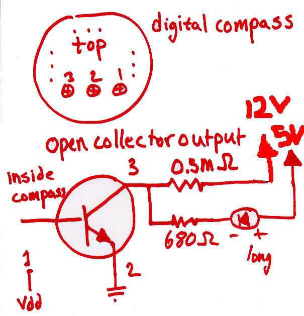
Each of the four terminals consistest of 3 leads. The output lead is
an open collector. The following circuit in the diagram is needed for the
output signal to go to 0 and 5 volts. In adition the LED is used for debuging.
[Diagram of compass (wire resitors, LED, and power)].
To know when it works answer the following questions.
Which way is South?
Rotate the compass. In what order to the leds go on?
More documentation
Dinsmore digital
compass
Additional data sheets in the lab.
Sonar Range Finder
The sonar range finder will be used to determine twice the distance
to the object infront of the sonar transducer (black disk). The sonar device
sends out 16 pulses at 49.5 kHz that travel to the object in front of the
sonar and back. The range finder is started by making INIT 5V. When
the pulses are recieved the ECHO out goes high. INIT has to stay high at
least until ECHO goes high. The sonar board operates this way when BINH
and BLNK are 0V. See the documentation for the other uses of the board.
Sonar
doc
Be care about touching the circuit board. The device needs 200-400V to works. Touching the sonar circuit board might give you an uncomfortable burn.
The interconnect to the sonar range finder board is:
| purpose | gnd | BLNK | INIT | ECHO | BINH | Vdd |
| pin / voltage | 1 / 0V | 2 / 0V | 4 / Input | 7 / Output | 8 / 0V | 9 / 5V |
The connections to sonar transducer (see transducer documentation):
E1 --> (+) brass tap
E2 --> (-) black tap
The ECHO output is an open collector output like the terminals of
the compass.
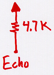
[Diagram for ECHO output]
To know when it works answer the following questions.
Connecting INIT to 5V will start the sonar range finder. You should
hear a scratching, which is the transducer sending off the 16 pulses. In
addition, ECHO goes high imidatly. Reset the sonar range finder by making
INIT 0V and ECHO should go low too.
More documentation
Polaroid 6500 boardtransducer
Wirz (same as above)
Additional data sheets in the lab.
You have to write a C program to test the sonar range finder. The program should time the difference between when INIT signal goes and when the ECHO signal goes high. Make several measurements to see if the readings make sense.
NW 3 m
You might have to use some logic to help determine when the state of the compass changes.
Note:
A transducer is a devicce that converts electrical signals to a different
form. The sonar transducer converts the electrical signal into sound waves.
