CSE466 Lab 1: “Blinker”
Objectives
Create a device that will blink a Light-emitting-diode (LED) at a rate of 1Hz. You should be able to modify the blink rate in software.
In this lab you will learn the following:
-
- Basics of the MSP430F2013 processor (Memory, registers, etc)
- Use of timer 1 to replace programmed loops
- Basic wiring on a processor IC
- Programming and debugging with the eZ430 programming dongle
Reading
Resources
Part 1: Using Code Composer Studio and the eZ430-F2013 Development Tool
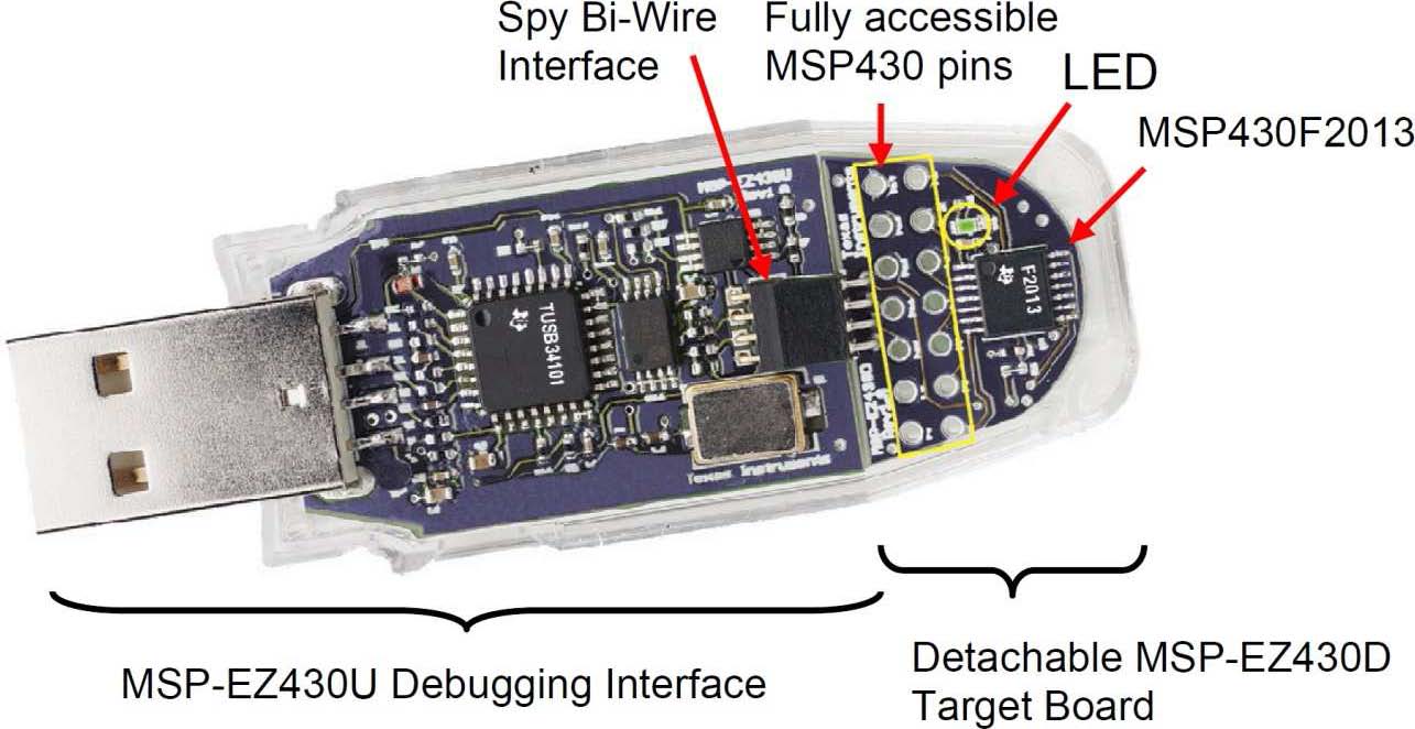
We will use the following hardware, from your kit:
Read all of the directions for Part 1 before doing
ANYTHING. Often the next step reveals why the current one is important.
This section demonstrates how to setup a project for the eZ430-F2013 and download the application to
the MSP430F2013. The sample program will blink the LED on the MSP-EZ430D target board.
- Plug in the MSP-EZ430U Debugging Interface with the target board attached.
- Start CCS (Start → Programs → Texas Instruments → Code Composer Studio v4 → Code Composer Studio v4).
- File → New → CCS Project.
- Name the project "Blink" in default workspace. Click Next.
- Project type: MSP430. Next. and Next.(no additional project settings).
- Set Device Variant = MSP430F2013; click Finish.
- Select Blink; do Project->Add Files to Active Project…
- Navigate to C:\Program Files\Texas Instruments\CCSv4\examples\msp430\example projects\msp430x2xx\C-source\msp430x2xx_fet_1.c
- Click Open to add the file to your project.
- In the file you just added, change line #21 from #include "msp430f2101.h" to #include "msp430f2013.h" and save.
- Use Target → Debug Active Target to begin the debug session.
- Use Target → Run to start the application.
- Observe blinking LED.
- Use Target → Terminate All to exit debug session.
- Use File → Exit to exit the IDE.
Congratulations, you've just built and tested your first MSP430 application.
Now, change i = 10000; to the largest number that the variable will contain. Re-compile and Re-run your code.
Question #1: What happened to the blink rate? Why?
Part 2: Wiring up the breadboard
- Read all of the directions for Part 2 before doing
ANYTHING. Often the next step reveals why the current one is important.
- Wire the circuit in this schematic
on your breadboard (this is identical to the MSP-EZ430D target board):
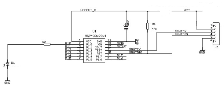
- Wire the circuit in this schematic
on your breadboard (this is identical to the MSP-EZ430D target board):
- The resistors value has been purposefully left off the schematic. You will need to consult the datasheet to find the chip’s electrical characteristics to determine the appropriate values of the reset pull-up resistor and the current limiting resistors for the LED. For decent brightness the LED should have around 5mA of current.
- Before powering on the breadboard, verify with a multimeter that there are no shorts between power and ground, and that power and ground are actually hooked up to the chips' pins.
- Turn on the eZ430U debugging interface, which will power up your breadboard.
- To verify that your hardware is working properly, program your wired up breadboard with the same code and steps that you used in Part 1 above. Your LED should blink. If not, check your wiring, and try again.
- Modify and re-compile your code so that the LED blinks four times faster than before. DEMONSTRATE THIS for checkoff.
Question #2: what is the power source for your processor?
Congratulations, you've just wired and tested your first MSP430 circuit.
Part 3: Use Timer 1 to do the same blinking
-
Read all of the directions for Part 3 before doing ANYTHING. Often the next step reveals why the current one is important.
Now you must modify your program to use Timer 1 to blink the LED.
HINT: experiment with the samples provided here, and see if you can modify an example to do what you need.
HINT: read the data sheet section on Timer 1. Don't panic: it's just a fancy counter...
- Plug in the MSP-EZ430U Debugging Interface with the target board attached.
- Start CCS (Start → Programs → Texas Instruments → Code Composer Studio v4 → Code Composer Studio v4).
- File → New → CCS Project.
- Name the project "Blink" in default workspace. Click Next.
- Project type: MSP430. Next. and Next.(no additional project settings).
- Set Device Variant = MSP430F2013; click Finish.
- Select Blink; do Project->Add Files to Active Project…
- Navigate to (the folders you un-zipped above): msp430x20x3_ta_02.c
- Click Open to add the file to your project.
- In the file you just added, change line #21 from #include "msp430x20x3.h" to #include "msp430f2013.h" and save.
- Use Target → Debug Active Target to begin the debug session.
- Use Target → Run to start the application.
- Observe blinking LED.
- Use Target → Terminate All to exit debug session.
- Use File → Exit to exit the IDE.
Now make your code blink slowly, 1 sec. on, 1 sec. off. Demonstrate this code to the TA. Hint: change your interrupt code to toggle the LED only 1 of n times...
Question #3: what is the clock frequency of the processor? Of the timer? How accurate is that clock? Where does that clock come from?
Part 4: Use the ADC to read a photo-resistor and change the blink rate
-
Read all of the directions for Part 3 before doing ANYTHING. Often the next step reveals why the current one is important.
- Based on the above, use msp430x20x3_sd16A_01.c as a template to measure the voltage created by a photo-resistor in response to light changes.
The photo-resistor is wired this way: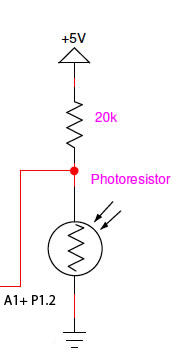 and should be connected to pin A1+ P1.2 of the MSP430F2013.
- Once the code runs as shown in the comments, combine this code with your timer interrupt code from Part 3. The light value from the ADC must change the blink rate.
Question #4: how many bits wide is the ADC data output in the 2013? How many bits do you need to modify the timer output?
E-mail a single .zip file containing all required documents to cse466-tas@cs.washington.edu
Demonstrate your
working system to a TA. You can either do this during this lab, or during the
first
1/2 hour of the next lab.