CSE 466 Lab 5: Introduction to the iMote2 and Embedded Linux
Introduction
Now that you've worked with a simple 8-bit microcontroller, we'll be exploring more powerful embedded devices. For the rest of the quarter, we'll be using the iMote2, which has a 32-bit, 415 MHz ARMv5 microcontroller (The PXA271), with 32 MB of flash and 32 MB of RAM. This microcontroller was designed for use in cell phones and PDAs. This lab will introduce you to the iMote2 platform, and using Linux as an embedded operating system.
WARNING: NEVER attach or detach the iMote2 from the debug board or the sensor board when power is attached. ALWAYS make sure you've unplugged ALL of the USB cables when connecting or disconnecting the sensor board or debug board.
Objectives
In this lab, you will learn:
- How to write user-level applications and load them onto the iMote2
- How to write, load, debug, and use Linux kernel modules
- How to use the PXA271's hardware timers
- How to control sensors and peripherals on the iMote2
- How applications communicate with devices in Linux
- The basics of the Linux character device model
Suggested Reading and Resources
Part 1: Getting acquainted with the platform
In your kit, you will have three boards:
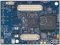
The iMote2 |
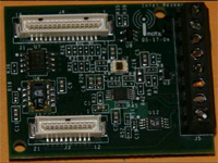
The Basic Sensor Board (BSB) |
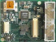
The Debug Board |
The debug board features the same USB interface chip you used in Lab 4. It lets you tap into the iMote2's serial ports, SPI bus, and I2C bus. In addition, it contains a JTAG interface for programming and debugging the iMote2. While you'll generally be using the USB Ethernet interface on the iMote2 itself to access the Linux console and program the iMote2, the debug board can be helpful for logging in when you cannot establish a network connection to the iMote2.
The Basic Sensor Board (BSB) contains an accelerometer, light sensor, temperature and humidity sensor, and a general-purpose ADC converter. In this course, we will primarily use the accelerometer on the BSB.
We've pre-loaded the Linux kernel, the filesystem, and the bootloader (BLOB) on your iMote2 using the JTAG interface. You should be able to follow these directions and log into the iMote2:
UPDATE (1 Nov 2007 at 4:51pm): If you're having trouble connecting to the iMote2, make sure that the network interface on the PC for the iMote2 is set up to use DHCP and not a manually-assigned address.
- Connect your iMote2 to the computer with a USB cable, press the power button, and wait for the LED to turn green.
- Open the Windows control panel and go to Network Connections. The iMote2 connection will appear as "Local Area Network Connection 6" or another high-numbered interface. Double-click it, and go to the Support tab. Make note of the IP address and close Network Connections.
- Launch PuTTY. If PuTTY is not installed on the lab machines, you can download it here.
- For the IP address, enter the value you noted in step 2, but replace the last number with 101. Click Open.
- Once you see the login prompt, log in with username root and password rootme.
Now that you've logged in to your iMote2, let's compile our first kernel module and user-level application!
UPDATE (30 Oct at 2007 5:01pm): It turns out there's a conflict between blink-mod.ko and the radio driver. For now, turn off the radio driver prior to attempting this section by editing /etc/modules, removing the 'tos_mac' line, and restarting the iMote2.
- Download and unzip the Blink application code to your attu account.
- To compile the kernel module, simply run make. This should produce a file called blink.ko, which is the kernel module.
- To compile the application, run:
/cse/courses/cse466/iMote2/cross-compiler/arm/3.4.1/bin/arm-linux-gcc -o blink-app blink-app.c
This should produce a file called blink-app, which is a user-level utility to set the blink rate.
- Copy the files over to the iMote2 using WinSCP3. To do so:
- Launch WinSCP3 from the desktop.
- Click "New."
- Enter the same IP address you used to connect with PuTTY for the hostname, root as the username, and rootme as the password.
- Optionally click "Save" and "OK" to save the settings for use next time.
- Click "OK."
- Drag the files from your O: drive (o:\unix\homes\iws\<username> maps to your Unix home directory) to the WinSCP window.
-
To load your kernel module, run insmod blink.ko on the iMote2 console. For more information on insmod, see the manual page.
- In Linux, like all other Unix-like operating systems, devices appear as special files. Devices can either be character devices, which act like infinite streams of bytes, and block devices, which communicate with fixed-size blocks of data. Devices are part of the regular filesystem namespace, usually appearing under the /dev directory. For each device "file," the filesystem contains an entry mapping that "file" to a device number, split into major and minor parts. Major numbers correspond to a particular kind of device, or a driver responsible for that device. Minor numbers correspond to specific instances of those devices, which are managed by a common driver. You can view these major and minor number by running ls -l /dev.
Since the number of major device numbers is small, well-behaved drivers request a major number when they are inserted into the kernel. Now that the kernel module has been loaded, we need to find out which major device number Linux has assigned to our new device. To do so, run cat /proc/devices. Under "Character devices," you should see a line like 254 blink. In this case, 254 is the major device number. Since we only have one blink device, we use 0 as the minor number. To make a filesystem entry for the blink device, run mknod /dev/blink c 254 0. This creates a character device named /dev/blink that points to device number 254,0. For more information on mknod, see the manual page.
- Execute ./blink-app 1 to blink the LED at 1 Hz.
- To remove the blink module, execute rmmod blink. For more information on rmmod, see the manual page.
Part 2: Extending the blink module
Now that you've successfully built a kernel module and an application that uses it, let's take a look at how it works. From there, you'll extend the blink module to drive three PWM signals to the tri-color LED (similar to lab 3).
Let's take a look at the blink-mod.c file.
- At the top, you'll notice several headers are included. The quick reference guides at the back of chapters 2-4 of Linux Device Drivers will tell you which header files you need for various kernel functions and data structures.
- The MODULE_AUTHOR, MODULE_DESCRIPTION, MODULE_VERSION, and MODULE_LICENSE macros embed information into the final kernel module file.
- The blink_fops structure points to supported file operations that can be performed on the device. A pointer to this structure is passed when registering the driver. For more information, see chapter 3 of Linux Device Drivers.
- The module_param macro lets you declare parameters that can be specified when the module is loaded. For more information, see chapter 2 of Linux Device Drivers.
- The blink_ioctl function receives all ioctl() calls on the device file from user applications. ioctl() is used for sending commands and setting and querying configuration information to and from the device when regular "read" and "write" semantics don't fit. For example, ioctl is used to eject CD-ROMs, set serial port baud rates, etc. For more information about ioctl, see chapter 6 of Linux Device Drivers.
- The blink_irq_handler function is called when the timer interrupt is fired. Note that on the PXA271, the interrupt for timers 4 through 11 are shared, and you must inspect the OSSR register to see which timer has fired. See the PXA271 Developer's Manual for more details. If the interrupt is not handled, IRQ_RETVAL(IRQ_NONE) is returned. If the interrupt is for this module, IRQ_RETVAL(IRQ_HANDLED) is returned. Chapter 10 of Linux Device Drivers has more information on interrupt handling under Linux.
- init_function is the function called when the module is loaded. Its responsibilities include allocating a major device number, allocating a character device for that device number, pointing the character device to the structure of available file operations, registering the interrupt handler with the kernel, and setting up the hardware timer. Note that unlike main, the function name isn't anything special -- a macro at the bottom of the file declares which function performs initialization.
- unload_function is called when the module is unloaded. It unregisters the interrupt handler and frees the character device and device number. Note that if a module doesn't clean up properly, the kernel will likely crash (called a "kernel panic") since data structures inside the kernel will point to code and datathat's no longer there. Like init_function, a macro at the bottom of the file declares which function should be called when the module is unloaded.
Now, your task is to modify the blink module and application so that you can set the tri-color LED to any color using PWM. Specifically:
- Modify the blink kernel module to generate PWM signals to all three LEDs, like you did in lab 3. You should be able independently control each LED’s duty cycle.
- Modify blink-app into a user-level application that sets the color output of the tri-color LED. You’ll need to extend the kernel module’s ioctl interface for this.
Part 3: Using the accelerometer
In this part, you'll finish implementing a driver for the accelerometer on the Basic Sensor Board, and write an application that converts accelerometer readings to colors, like in lab 3.
- Download the accelerometer skeleton code here. It should contain the following files:
- st-accel.h -- header file for accelerometer driver, shared between the module and application
- accel.c -- accelerometer driver skeleton code
- accel-dump.c -- program that continually reads and displays accelerometer values
- Before getting started, here's some things to note about the skeleton driver:
- In addition to the ioctl syscall, the read syscall is implemented. The driver emits a stream of sensor readings that can be read with read. If no sensor readings are available, the application sleeps until data is available.
- To read from an accelerometer register, use the accel_read_reg function. To write to an accelerometer register, use the accel_write_reg function.
- A GPIO interrupt is triggered when data is ready.
- The ssp_* functions are part of the Linux kernel, and interface with the PXA271's synchronous serial port controller. See /cse/courses/cse466/iMote2/sources/linux-2.6.14/include/asm/arch-pxa/ssp.h for more details.
- You can write data into the circular buffer read by the application by calling write_data_into_buffer.
- Since the driver simply produces a stream of bytes, the accel-dump application expects two sync bytes to precede each accelerometer reading (0xA5 0xA5).
- Implement accel_irq_handler and accel_ioctl in accel.c.
- Test your module with the provided accel-dump application.
- Create an application that translates the accelerometer readings into color values. You do not need to do any fancy HSV to RGB mapping -- simply using each axis of the accelerometer to control a single color is sufficient.
Part 4: Module interoperability
The PWM module you wrote in Part 2 uses Timer 4 to generate the timing for your pulse-width modulation. The radio driver also makes use of a hardware timer, Timer 5, for functions like timeouts and binary exponential backoff. While these are two separate timers, they share the same IRQ in the XScale architecture. In order to use both your PWM module and the radio driver at the same time, you need to make a few changes to ensure that this IRQ is properly shared between the modules.
- There is a bug in the skeleton code that was distributed for your PWM module. In the IRQ handler, the interrupt is acknowledged with OSSR |= OIER_E4. Bits in OSSR (like many other registers in the PXA271) are cleared by setting the bits to clear to 1. Bits that are set to 0 are left alone. We want to clear the bit for the timer 4 interrupt flag, which is defined by the constant OIER_E4 as bit 4. We do not, however, want to clear any other bits, which will cause unexpected interactions between modules. Change the |= to = to solve this problem.
- The PWM module needs to tell the kernel that it is willing to share the timer IRQ when it requests the IRQ, or you will not be able to load it at the same time as other modules that also use the timer IRQ, such as the radio module. In the init_function function, change the third argument for the request_irq() function call (which is currently 0) to SA_SHIRQ.
- The verison of the tos_mac.ko radio driver module that was flashed onto the iMote2s before you received them also has several interrupt sharing-related bugs. Download the new version and place it in /lib/modules/2.6.14_r1.0/kernel/drivers/tosmac.
- Make sure that the tos_mac module will be loaded at startup by editing /etc/modules and adding a line for tos_mac if there isn't one already. Make sure you restart your iMote2 to load the new module (or run `modprobe tos_mac`).
You should now be ready to move on to the next section and begin using the radio driver.
Part 5: Using the radio
In this part, you will be introduced to the radio functionality of the iMote2. We will give you example code for sending and receiving from the radio, but you will have to come up with your own packet structure for your communications protocol.
- Download the radio code here and un-zip it in your attu account. It should contain the following files:
- tosmac.h: header file for the radio driver
- count_and_send.c: a program that increments a counter at 1Hz, displays the counter value as a color on the LED, and sends the value with the radio
- receive_to_led.c: a program that receives the count via the radio and displays it as a color on the LED
- led.h: a header file for the simple LED driver that these programs use
- a Makefile that will build the sample applications
- Change the GROUP_NUMBER constant in both .c files to your group's number. This will let you send and receive messages on a channel unique to your group, which is helpful when you are trying to debug your radio code. Note, however, that your communications protocol in your own programs, when finished, should use some kind of unique identifier or address and ignore packets that are not your own. Your unique channel (again, for debugging purposes only) will be your group number plus 11.
- Run make to compile the applications. Load count_and_send onto one of your iMote2s and receive_to_led on the other. (Make sure that you've updated the tos_mac driver on both iMote2s, and that you are not running your PWM driver, which will interfere with the basic LED driver.)
- You should see the LEDs on both iMote2s updating at the same time to the same colors. The sending iMote2 will also print out the current value that it is sending, and the receiving iMote2 will print out the value that it is receiving.
- Once you're convinced that the programs work, change the channel back to 11 (set GROUP_NUMBER to 0) and implement a communications protocol so that your receiving iMote2 will only update its LED based on messages it receives from your sending iMote2, even when there are several other iMote2s transmitting on the same channel. The design of your protocol is up to you, but you should use at least a unique identifier (use your group number) and an arbitrary node ID unique to each of your iMote2s.
Note that the tos_mac driver does not implement the full 802.15.4 standard or the entire ZigBee protocol stack. Regardless of what you set the destination address to in your applications, all packets will be sent as broadcast (0xFFFF). As such, you cannot rely on the 802.15.4 addressing scheme to send packets to a particular iMote2; you must implement this in the data payload.
Part 6: Putting it all together
In this part, you will combine the elements from Parts 1-5 and add bi-directional communication between your iMote2s.
- Using the modules you have developed so far, create two programs to run on your iMote2s:
- The first program should read your accelerometer value and send readings out over the radio using the packet structure you've developed.
- The second program should receive the accelerometer readings via the radio and update the color of its LED using your PWM driver.
- Your receiving iMote2 should also read from its own accelerometer, and transmit a "stop" signal to the sending iMote2 and turn off its LED when it is turned upside down. When it is turned right-side-up again, it should transmit a "start" signal.
- The sending iMote2 should react to a "stop" signal by ceasing to transmit packets and updating the color on its own LED instead. When the "start" signal is received, it should turn off its own LED and begin transmitting packets with accelerometer readings once again.
While you're designing your programs, you should keep the following things in mind:
- In the sample code, reading from the tos_mac driver is done in blocking mode. That is, when you try to read from the device, your program will wait until a packet has been received before continuing on to the next line. This works well for uni-directional communication, but not as well for bi-directional communication. See the man page for open for more information on non-blocking I/O.
- You probably don't want to send packets as fast as you possibly can. Your sending iMote2 should wait some amount of time between packets that still feels responsive, but is not as fast as possible.
- Your final implementation should function on channel 11 and ignore packets sent by other groups.
Deliverables
You have two weeks to complete this lab. There are no deliverables for the first week, but to stay on schedule, you should have working LED PWM and accelerometer drivers.
Turn in all required documents via Catalyst, or as an e-mail attachment to cse466-tas@cs. For all files turned in, the comments at the top of the file should contain:
- Both partners' full name, login and student number.
- The lab number and the part of the lab (e.g. "Lab4, Part2").
- Demonstrate your system of sensor to radio to radio to LEDs to a T.A. You can either do this during lab, or during the first 1/2 hour of the next lab.
- Grading will focus on whether it works, and reasonable responsiveness.
- At the end of the second week, you should turn in source files for:
- all of the kernel modules you developed or modified, and
- the user application you wrote for Part 6.
You should create a .zip or .tar archive of all of the files you are turning in.