CSE466-03au Lab Assignment 2
Objectives
Create a device that will count from 00 to FF on two 7-segment led displays (one will be the high nibble and the other will be the low nibble). When either end of the count is reached, it should wrap around and start counting from the beginning. Hint: the ATMega16 is an 8-bit processor, so the registers are only 8-bits wide. This fact should make the wrapping task easier. There will be an example setup in the lab that you can use as a reference.
In this lab you will learn the following:
- AVR assembly
- Binary to hexadecimal 7-segment conversion
- Become familiar with AVRStudio 4 (which has a simulator)
Suggested Steps
- Wire the circuit in the schematic on your breadboard. Note that the pot, photoresistor, and buttons are for the next lab, so you won't need them this time. Just make sure you leave enough space on your board so that you can add them next time. Power off the breadboard and wire up the seven segment displays. Note that one is going to represent the high nibble and one is going to represent the low nibble, so it would be nice if the 7-segment displays were either next to each other or otherwise aligned with each other so that they're easy to read.
- Verify with a multimeter that there are no shorts between power and ground, and that power and ground are actually hooked up to the chips' pins.
- Open AVRStudio 4 and follow these instructions to setup a new project:
- Click on the “Create New Project” button that is on the window that appears when it opens.
- The Project Type is “AVR Assembler”. Give the project a name and change the location to one of the lab partner’s network share. Then hit next.

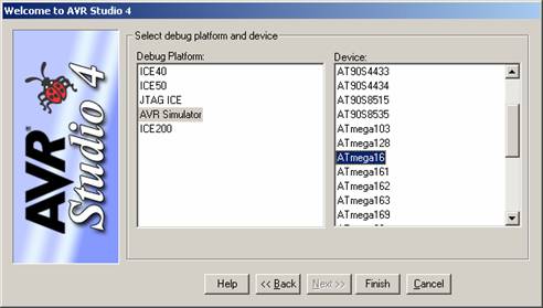
- Select “AVR Simulator” as the Debug Platform and “ATmega16” as the Device then hit finished.
- You should also verify that you output will be in .hex so go to the Project menu and select AVR Assembler Setup. The Additional Output file format should be set to “Intel intellect 8/MDS (Intel hex)”.
- Write a simple
loop in assembly that blinks one of the segments. Skeleton code sample is here.
- Implement a lookup table to convert a 4-bit nibble (in binary) to a hexadecimal number.
- Using the lookup table, finish implementing the hexadecimal counter in assembly code to take the current value of the counter and display it on the two seven-segment LEDs.
- Use MegaLoad to load the hex file to your board.
Helpful Hints
- Instruction set summary is on page 303 of your course pack
- Detailed instruction descriptions available at Atmel's website. Please don't print out (149 pages) as the rest of your programming will be in C.
- General purpose registers are r0-r31, watch for instructions that only operate on some of them (ldi, load immediate, only works on r16-31)
- Include [.include "m16def.inc"] to get logical names [PORTA] for registers (as opposed to having to use addresses [$3B])
- When making the hex letters, they should all be uppercase except for the letters b and d which should be lowercase.
Deliverables
Calculate the amount of current flowing through the seven-segment LED’s when it is turned on. Put this calculation at the top of your assembly file in the comments.
Demonstrate your working system to a TA. You can either do this during this lab, or during the first 1/2 hour of the next lab. Counting should happen at a leisurely pace (between 0.5 and 2 Hz).
Turn in hardcopy of your commented assembly code that should include the following:
- A lookup table
- Current Calculation (see above)
Other Resources
LED Data Sheet
MAX232 Data Sheet
Connecting LEDs app note
Lab 2 schematic
End