
We will be rigging Marc,
- FIRST - create a Joint Chain which will serve as Marc’s skeleton structure,.
- SECOND - insert IK Handles so that you can move several joints at once and strike a pose,
- THIRD - use skinning to attach your skeleton to the model (skin),
- FOURTH - use constraints, which can be downloaded here spline objects, to move your rigged model easier.
Compare what we do in this tutorial with that of the fully rigged Marc character (will be available soon) we give you in the animation exercises. The rigging we will be doing in this tutorial is fairly simple to follow. The fully-rigged Marc character is much more complex. The more complex your character's skeleton, the more control the animator has in manipulating its movements. You can obtain an empty "Marc" file by clicking here. Some key points to remember when rigging a character:
- As you create joints, go through the painful process of NAMING them. It's probably easier to do it at the same time. But by naming all the joints, you'll be able to select the joints you need in the future as you animate your character.
- Note that Marc is centered directly over the point of origin. This is so that you can use the grid-snap quick key ("x") as you place his central joints.
- Hierarchy is important in rigging a character. The wider end of the "bone" tells you which joint is higher in the skeleton chain. In the picture below, you know that the top-most joint of the chain is the joint to the far left.
A parent joint is a joint higher in a skeleton's hierarchy than any of the other joints that are influenced by that joint's action. Joints below a given parent joint in the hierarchy are called child joints. For Marc, the top-most parent joint is the Root joint (a character can only have ONE root joint), while the bottom-most would be the fingertips, the toes, or the top of the head.
- When you create a joint chain that you will use IK Handles for, have the joint slightly rotated at an appropriate angle to make posing with IK handles easier.
- Have we mentioned labeling all your joints?
- SAVE OFTEN!!! Especially after doing some major chaining, before and after skinning, before and after creating IK handles, and before and after creating constraints. There will be many times when you're creating constraints and you realize that you messed up all the way back when you were chaining and you're wishing that you had saved more often....
The Basics of Creating a Joint Chain
To create a simple joint chain like the one above:
·
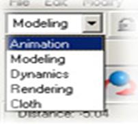
 Make sure you're in the Animation Menu set.
·
 Select Skeleton > Joint Tool.
· Click where you want to create a joint. Click again where you want to create the next joint in the joint chain.
· Press Enter when you're done making all the joints you want.
Manipulating Joints and Joint Chains
- Moving joints while joint tool is active: Click the middle mouse button once. Move the joint with the middle mouse button. Continue clicking with the left button to continue with your chain.
- Moving joints if the joint tool is no longer active: To move only one joint without moving everything else, select the joint, then hit the Insert key on your keyboard.
- Selecting parent and child joints: Use the up and down arrows to move through the hierarchy of the chain.
- Rotating a joint's local rotation axis: Select the joint, then from the menu, choose Display > Component Display > Local Rotation. To select the axis itself, you need to be in the "components" selection mode. Right click the "miscellaneous" button (the one with the question Marc) and check "Local Rotation Axis". You can now rotate it.
- Inserting a joint into the joint chain: It's best to do so before you add IK handles (you'd have to redo them) and before skinning (would lead to undesirable deformations). Select Skeleton > Insert Joint Tool. Move the cursor to the joint you want to be the parent of the new joint. While pressing the left mouse button, drag to where you want the new joint(s) to be. When you're done, hit Enter or select a new tool.
- Removing a joint in a joint chain: You shouldn't remove skinned joints and you can only remove joints one at a time. Select the joint you want to delete, then select Skeleton > Remove Joint. The bone of the joint's parent is extended to the joint's child.
- Changing the display size of the joints: Select Display > Joint Size. Smaller percentages come in handy when manipulating fingers and toes.
Part I - Setting Up the Skeleton
When setting up the skeleton, we're simply laying out where the bones should be.
We'll start with the Root and work outward from there. Utilize the grid-snap "x" tool especially here to ensure that you're placing your joints at the exact center of the body. The root is the topmost joint (parent of them all). We begin by placing our first joint around the waist, then working upwards creating a joint for the torso, the chest, the neck, and the head. Since we are snapping to the grid, the joints are centered in the X and Z directions, but not located correctly in the Y direction. This can be corrected as you work along the chain. As mentioned above, clicking the middle mouse button will activate the "Move" tool while the "Joint" tool is still active. Click the middle mouse button once, move the joint in only the Y direction by clicking the middle mouse button on the Y axis of the Move control, then continue building the skeleton by clicking the left mouse button.
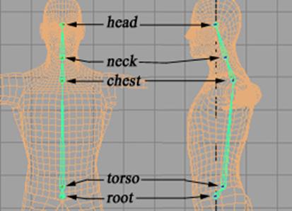
Now that you've placed your joints from the front view, switch to the side view and move the joints so that they are better placed on the body. Remember that you can move one joint at a time by selecting the joint and hitting the Insert key on the keyboard. Marc should look something like this:

Again, this is a very simple skeleton. If you compare this with the fully rigged Marc, you'll see that the fully rigged Marc has two head joints (head, forehead), two neck joints (neck, neck2), one chest joint (sternum), three back joints (upback, midback, lowback), one torso, and one root joint.
An alternative way to create this "spine" is from the side view. This way, you know that the joints will be placed right on the Y axis.
Next, from the front view, lay out the bones for the left arm (lshoulder, lelbow, lwrist) and the left leg (lhip, lknee, lankle). You only need to do one side since we will be mirroring it to the other side. Placement of these joints will depend upon how naturally his skin will bend around the joints. They will probably be moved after you've skinned your character through trial and error, but for now, simply place them at approximate locations.
Switch to the top view. Move the arm joints until they are about centered on the arm. Switch to the side view. Move the leg joints so they are located more towards the front of the leg. Your joints should look something like this:
There are two reasons for the slight bend in the elbow and knee joints. The first one is that people's joints are never really completely straight when in a normal stance. There is some slight bend to them. The second reason is that it will help you later on when you put on your IK handles. (When doing IK handles, a preferred angle can also be set if your joints are completely straight through the tool Skeleton > Set Preferred Angle)
Select lshoulder and then select chest, and connect them with Skeleton > Connect Joint (be sure that the option "Parent Joint" is selected for this tool). A bone should appear between the two joints.
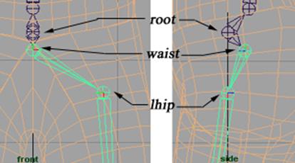
Beneath the root joint, create another joint named waist. Select waist and then root and connect them. Then select lhip and then waist and connect them. Your connection should look something like this:

You can think about the root as having two subroots, the torso and the waist. The torso controls the upper body movements while the waist controls the lower body movements.
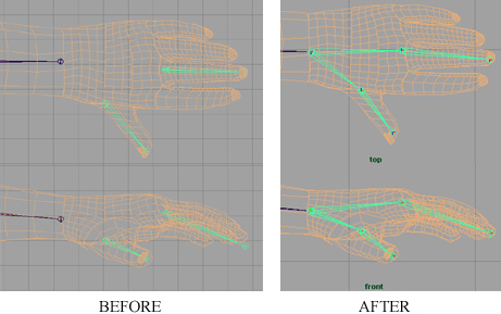
Next, add the hands and the feet. Again, we will keep this simple. As with the rest of the skeleton, there are many ways that the hand can be done. Below is an example taken from Alias|Wavefront of a hand skeleton (left) compared with the way Marc is rigged (right).
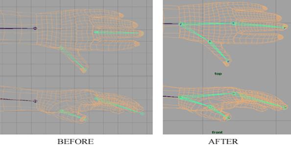
For our purposes, we will only create the lthumbBase, lthumbTip, lhand, lhandTip. From the front view, create one joint chain for the thumb, and one joint chain for the hand. Then from the top view, position the thumb chain over the thumb and the hand chain around the middle finger. Attach these chains to the wrist.
REVERSE FOOT
The feet are a little more complicated. Although the rigging on the left would be the natural rigging progression of beginning at the root of the body and placing joints until reaching the very end, this rigging alone does not work as well as Marc's feet which are set up as Reverse Feet. When you animate a walking character, you need the feet to plant itself while the other foot is lifted into position. In the time it is planted, the foot needs to roll from the heel to the toe. A Reverse Foot skeleton is the ideal technique for creating these conditions. First, from the side view, create heel, ball and toe.
![]()
![]()
Then create
a separate joint chain, beginning with the heel again (except the
"ball" will be after the toe), named RevHeel,
RevToe, RevBall, and RevAnkle.

ALIGNING
REVERSE FOOT WITH REGULAR FOOT
From the side view, align the RevAnkle joint so that it is in the same plane as the foot. Do so by selecting the RevAnkle joint, then hold down “v” and middle mouse button drag RevAnkle toward Heel joint until it is right on top of it. Go to perspective view, you’ll see that the RevAnkle joint is right on top of Heel joint. Translate RevAnkle joint down the y-axis until the entire reverse foot is about 2 grid lines below the heel joint.
Select RevHeel, then hold down “v” and middle mouse button drag RevHeel toward Toe joint until it is right on top of it.
Repeat for RevBall over Ball and RevToe over Toe. You should end up with the following.
We will finish the foot above when we set up IK handles. (NOTE: It's important that your joints for at least the heel and the toe are located exactly on axis. This way you know when your foot is contacting the ground. I know it isn’t illustrated here, but you should do it anyhow.) But before we do so, we must zero out to all the joints, see below.
Setting up joint limits
Because the position of the joints changed because
we used the Move tool on them, the orientation of their local rotation axes was
not affected and are no longer aligned with the bones. For example, as
you place joints (and assuming that the Joint Tool's Auto Joint Orient tool
setting is set to the default of xyz), the X-axis of
each joint's local rotation axis will point into each joint's bone. When
you move (translate) a joint, the local rotation X-axis no longer points into
the bone, which is what you want. The fastest way to reorient the joints
is typing in the following MEL command in the command line (bottom of
screen): joint -e -oj xyz -zso
-ch;

-oj flag
stands for orient joints, xyz
specifies the orientation, and -zso specifies that the local
scale axes also be reoriented. The -ch flag specifies that
the command act on the selected joint and on all the joints below it (all the
child joints) in the skeleton's hierarchy. If you only want to reorient
the selected joint, don't include the -ch flag.
Before you run this command line, select all the joints you want to reset and Edit>Freeze Transformations. Run the command line. Now all the local axes are reoriented so the the x-axes points into the bone. It's best to choose the joints where the angle of rotation is important, such as the joints in the shoulders, elbows, fingers, and knees. It's not such a good idea to choose the root joint to choose everything since it will mess you up later on under "Part IV - Constraints". If you're not sure which joints to choose, just run the command as you run into joints that you need to reset.
Now set up the joint limits. By setting up the joint limits, you are limiting how much rotation a joint can have. For instance, a person can turn his/her head a certain distance before he/she feels the resistance that keeps us from spinning our head in our neck like an owl can. So you would set up a limitation on the neck joint to prevent your character's head from spinning unnaturally around in its joint.
We'll start with the lpalm. Take your own fingers (you are the best source to base your character's movements on) and push it as far backwards to your arm as you can. If you are flexible, you can get a 90 degree rotation max.

Now bend your fingers all the way forward. You are most likely able to close your fingers over your palm. But it isn't exactly as if the finger joints are 180 degrees from its upright position. We will estimate 120 degrees.

Open the Attribute Editor for lpalm.
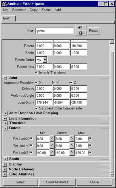
Open the "Limit Information" arrow. Here the "Rotate" attributes are by default opened with the Limit Information. For "Rot Limit Z", check the box for "Min" and "Max". If you click the arrows to either side of the "Current" column, that value translates depending upon which arrow you click. Or you can type in values for "Min" and "Max" manually. Set the "Min" value for Z to be "-90" and the "Max" value for Z to be "120". Since the lpalm cannot really rotate in either the X or Y directions, click those check boxes so that their "Max" and "Min" values equal "0".
So if you now select the lpalm joint, it can only rotate in the Z-direction between the values of -90 degrees and 120 degrees, and can never rotate in any other axes besides the Z-axes.
Do this for all joints. Determine if it's a joint that you want to rotate or twist, and figure out the angle using a combination of what you estimate you are physically capable of doing and what looks about right on the computer.
If you haven't done so already, save your work.
Mirroring joints
Now you should have a set up for the left side of Marc. Now you want this duplicated to the right side of Marc. The highest parent you want duplicated in the arm is the lshoulder joint. Select lshoulder, then the tool Skeleton > Mirror Joint*. (* denotes to select the option box). Verify that the axes set for the tool is over the YZ axes (assuming you have drawn Marc facing the Front view). The joints are mirrored over to the right side. The highest parent you want duplicated in the leg is the lhip joint. Select lhip and mirror the joint. Now you have a complete skeleton. You will have to rename these joints to read rhip, rknee, etc. to denote the right side joints. And if you haven't done so already, name the rest of your joints. Don't forget to mirror and rename the reverse feet as well. Save your work again.
Part II - Setting Up the IK Handles
An IK handle is like a wire that can run through a joint chain, providing a way for you to pose the entire joint chain in one action. As you pose and animate the joint chain with the IK handle, the IK handle automatically figures out how to rotate all the joints in the joint chain by using its IK solver.
To set the leg IK handle for the left leg, select the lknee joint, then Skeleton > Set Preferred Angle. This will give the IK handle a starting rotation that will be used as the target rotation by the IK solver. Select the lRevHeel joint chain and hit "CTRL+h" (this is similar to selecting Display>Hide>Selection) Select Skeleton > IK Handle Tool (make sure the tool's IK solver is set at "ikRPsolver"). Click on the lhip joint and then the lankle joint to create an IK chain. Rename the chain to lankleIK. You will use the lankleIK to move the leg around, rather than choosing joints.

Set the right leg IK handles and both arm IK handles in a similar manner.
Change the IK Handle Tool setting to "ikRPsolver" (RPsolver = Rotate Plane solver, SCsolver=Single Chain solver). Click on lhip then lankle. An IK Handle has just been created from the hip to the ankle. Reactivate the tool (either reselect the tool from the menu set or type "Y" which reactivates the last menu command) and click make IK Handles from ankle to heel, heel to ball, and from ball to toe.
From your hypergraph you’ll see a row of newly created IK Handles. Grab all of them and group them all under the node “IK Handles”.
FINISHING UP
THE REVERSE FOOT
Select RevHeel and IK Handle on the Toe, and click on Constrain >> Point. Repeat for RevBall and IK Handle on the Ball and RevToe and IK Handle on the Heel.
That’s IT!!! Your reverse foot is done. Take a 10 minute break and come back to finish the rest of it up.
Your outliner should now look something like this:

Notice that the ArmIK's are not grouped under anything.
Part IIi -Joint Clusters
Move Marc's arm around. You may find that the shoulder breaks. This can happen any place the model bends. To fixed this you need to change the weight a joint has on the control points of the model or which joint controls the points.
To edit membership (which joint controls the a point) go to Deform->Edit Membership Tool, then select the joint. All the points the are controlled by this joint with be highlighted. At this point you can hit shift and the left mouse button to add a point to the joint.
A point is controlled by a joint it is given a default weight of one. The weighting-value controls what percentage of a joint's translation and rotation is applied to the point. To change the weight go to window->General Editors->Component Editor then select the "Joint Clusters" tab. Now select the point that you want to change the weighting on. Slide the scroll bar until you see a box value in it, this number can have a value between 0 and 1.
Getting the model to look right can take some time.
Part III - Skinning
Binding the Skin
First, MAKE SURE THAT EVERYTHING WORKS THE WAY YOU WANT IT TO. Or at the very least, save your file before you attach it to the skin. So far you should have been saving files named things like, "MarcSkeleton", "MarcLimits" etc, or even "MarcTake01", "MarcTake02" etc so that you'll always know where in the process you are when you save the files.
Also, if you are using a character model besides Marc, be sure to delete the histories first BEFORE you bind it. This is very important!!!
Grab your entire Skeleton structure and Marc,
Select Skin >> Bind >> Smooth
Bind. Marc is not bound to the
skeleton. If you select a joint and move
it, Marc should move along with it. You
may notice that there are some kinks to this sort of binding, i.e. the shoulder may
break, neck moves weird. Use the
following tools to paint weights, under Skin
>> Edit Smooth Skin >> Paint Skin Weights Tool. In fact, this part is so confusing,
you should just ask your TA or Darrek for assistance. In
the option box, change the "Bind to" option to "Complete
Skeleton" and check the "Colored Joints" option. You
should now have Marc that looks something like this.

So now if you move the joints. It will move a corresponding geometry related to the joint. Of course he will not move as well as the Marc file you've worked with for the poses, only because his skeleton is extremely simplified. But you have now created a skeleton and skinned him. It's now a matter of making him a little easier to work with.
Part IV - Constraints
Import the file spline_objects.mb. What this file is are objects created with NURBS curves, rather than surfaces. The reason for this being that you can easily hide NURBS curves from your windows option rather than hiding NURBS surfaces, since that's what your character might be made from. For this exercise, the diamond will represent things that can be translated and rotated, the sphere will represent things that can only be rotated, the box will represent things that can only be translated, and the trapezoid will represent the elbow and knee constraints, which should really only be translated. Notice that there are color/layer assignments on them as well. When a constraint is located on the right side of the body, it should be put on the RIGHT layer (vice versa for LEFT). When the constraint is at the central part of the body, then it should be put on the CENTER layer.
To import them, download them first and then go to File>Import*. Make sure the "File Type" is set to "mayaBinary". Click the "Import" button. Find the file that you downloaded (spline_objects.mb), and click "Import". The objects should appear at Marc's feet. They need to be scaled up in size as well. The size that you scale them to will depend on what their location is on the chain of hierarchy. The higher the hierarchy, the larger the object. This is just so the user interface is that much easier.
We'll start with the root node. Select a diamond, copy it, and scale it up some. Rename it ROOTCON. Select the root joint, then ROOTCON and point constrain it (Constrain>Point). This is merely to locate the constraint exactly where the root is. In the outliner, select ROOTCON_pointConstrain1 which is a child under ROOTCON, and delete it. Select ROOTCON and translate it in the Z-direction 20 units. With ROOTCON still selected, select Modify>Freeze Transformations. What this will do is make all translational, rotational, and scale values to zero in the exact spot and size that ROOTCON is located. Now select ROOTCON then the root joint, and then point constrain them. Marc will move forward since his root joint is trying to go where the constraint is.

Select the root joint and open the Attribute editor with CTRL-a. Click on the tab that says root_jointConstraint1. Under "Point Constraint Attributes", type in "-20" for the Z-value. Marc should move back to his original position.

Now select ROOTCON and then the root joint, then Constrain>Orient Constrain. Now you can use ROOTCON to translate and rotate Marc as a whole.
To set up the left knee, select a trapezoid, copy it, freeze transformations, and rename it LKNEECON (remember to put it under the LEFT layer). Select the knee joint, then LKNEECON, and point constrain it. Delete the point constraint from the Outliner. Now translate LKNEECON so that it's in front of the knee, about 15 units. Freeze transformations on it. Select LKNEECON, then lankleIK. Then Constrain>Pole Vector. Now when you move the foot (remember, you have to move the foot with lRevHeel at this point) you can also position the knee. Do the same thing for the elbows and for the right knee.
Set up the feet and arms with the boxes. This time, use only point constraint. It might help to relocate the point of origin of the boxes if you want it to align with the heel.
Set up the torso and waists. This time, use only orient constraint.
The eyes can be point constrained to the top head joint and then offset.
Parent any head constraints under the torso constraint. Parent Torso and Waist under the ROOTCON. Parent the elbow constraints under the hands, knee constraints under the feet. Create one big TOPCON above Marc's head, and parent the root, the hands, and the knees under this.
If you still want to rig some more, here is a link to rigging cars and other things. http://www.gignews.com/kappmarch02.htm