|
Tutorial : How to create a flag using soft bodies Date Assigned Due Date: End of Quarter
|
|

In this lesson you will learn how to create a flag by turning a NURBS plane into a soft body. You will then learn how to adjust the goal weights of the flag to cause the flag to react to dynamic forces such as Turbulence and Wind. You will then create a surface emitter, and position it to create the effect of rain on a windy and cloudy day.
Part 1 - Flag Tutorial
Step 1: Open the file and edit the flag geometry
Open the file tutorial2.mb. The file has the environment, the flag pole, and the plane that will become the flag already modeled and shaded. You will also notice that the time slider is set from 0 to 250 frames. This will be the length of your animation.
|
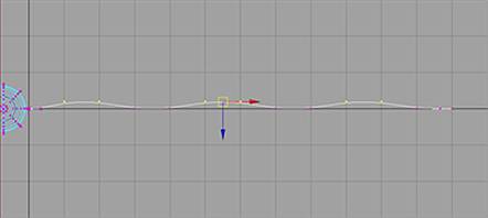
We will first be using the top view to change the shape of the flag. First select the flag (it's lying on the axis so is hard to see). Next press F8 to go into the Component Mode of selection. In your top view pick the following three pairs of C.V's as shown in the image and move them up slightly. |
|
|
Again in your top view pick the remaining three pairs of C.V's as shown in the image and move them down slightly. This creates some basic wave to the flag to make it look more natural. Now press F8 to return to object mode. |
|

Step 2: You will now convert your plane into a soft body.
|
If not already selected, select the dynamics menu from your Menu set to make it active. Next, switch back to your front view. Select the flag surface and in your dynamics menu click on Bodies>Create Soft Body-Options. In the option box set the following:
Setting the creation options Make Copy Soft to On makes a copy of the object a soft body without altering the original object. Switching Hide Non-Soft Object to On will hide the non-soft copy of the object so that only the soft body is shown. Turning Make Non-Soft a Goal to On to on will make the soft body trail or move toward the goal object made from the original or duplicate geometry. You are able to control how closely the soft body follows the original by adjusting the goal weights on the C.V.s. A goal weight of 1.0 follows the original exactly, a goal weight of 0.0 will not follow the original and will be completely influenced by dynamic forces. |
|

Step 3: Create Dynamic Fields to control the motion of the soft body.
|
With nothing selected, select Fields->Create Gravity, Fields->Create Turbulence, and Fields->Create Air to create three dynamic fields: a gravity field, a turbulence field, and an air field. Create explanation of gravity, turbulence, air, & drag Use the Outliner window to select the air field. Move the air field to the middle of the flag in the front view, and slightly behind the flag in the top view. Select and move the turbulence field into the the very center of the flag. The next step is to tell Maya to have the fields influence the soft body. Select the Windows->Relationship Editor->Dynamic Relationships. menu option. Scroll down to select copyOfFlag, highlight the fields in the right hand window. Now, close the window. The fields will now influence the flag.
|
|

Step 4: add springs to the soft body for a more realistic looking movement.
|
With the copyOfFlag selected, Click on Bodies->Create Springs->Options. Set the Max Distance to 1.0, and set the Wire Walk Length to 3. Click on Create. The Wire Walk Length determines how many springs are created between edge particles. For instance, for each edge particle, the value 3 creates springs to all edge particles within a distance of three particles. These springs will give the flag internal structure and will improve upon the deformation control. The Max Distance attribute tells Maya not to create springs if the distance between the two particles that may be potentially connected by a spring is greater than the number specified in the field. Playback your scene. While these forces are connected and acting on the soft body, you are not getting any results. This is because of the fact that when you created the soft body, you assigned a goal weight of 1, which results in the soft body always achieving its goal of maintaining it's original shape. You will need to adjust the goal weights of the individual particles so that the soft body will not always achieve its goal. For this you will use the component editor to assign goal weights to the vertices of the flag. |
|

Step 5: Edit the goal weights of the flag.
|
We will now edit the goal weights of the flag on a per particle basis, to allow the forces to take a larger effect on the flag. With copyOfFlag selected, press F8 to go into component mode. Hold down the Shift key, and select all of the particles in the first 2 columns, except for the first two vertices in the upper left hand corner, and the first two vertices in the bottom left hand corner (see figure). |
|

|
Next select the Window->Attribute Editor menu. Under the Per Particle Attributes section of the attribute editor you will see goalPP. Right click in the box and select Component Editor. The component editor should now appear. The particles tab should already be selected, but if it is not, then please select it. Scroll to the right until you see the goalPP column. This column contains the goal weights of the points you have selected. Change the goal weights of all of the highlighted particles to 0.4. Luckily you don't have to type in each cell. Select the goalPP cell for the first particle, then hold down Shift and press the Page Down key repeatedly until you've selected the whole column. Now type 0.4; when you hit Enter all cells will be changed. Now for the final 10 columns, select 2 columns of particles at a time, and sets their goal weights to be 0.30, 0.26, 0.22, 0.18, 0.12 respectively. For the last column, select the particles and set the goal weight to 0.10. By doing this, we cause the C.V.'s closest to the flagpole to be most strongly bound to the original flag geometry. Points at the far end are only minimally bound, and so will be more strongly affected by the forces. |
|
|

Step 6: Editing the attributes of your dynamic forces.
|
Now you will edit the attributes of the dynamic forces in your scene to make the flag behave correctly. First select the turbulence field, and then select Windows->Attribute Editor. In the attribute editor, set the magnitude to be 75, the attenuation to 0, and the frequency to 1. Now select the air (wind) field. In the attribute editor, set the magnitude to 60, the attenuation to 0, and the direction to 1.0, 0.0, 1.0. Finally, select the gravity field. In the attribute editor, set the magnitude to 100. The turbulence field causes random distortions over the surface of the flag. The air field simulates a wind coming from behind the flag and to the left. Finally, the gravity field causes the free end of the flag to realistically dip down relative to the end at the flagpole. The attenuation of zero means the forces will apply equally throughout all space instead of dying off. Play back the animation. |
|

Step7: Adjust the phase of the turbulence field.
|
If you playback the animation at this point you will see that the "shape" of the turbulence seems to cycle over and over and as a result you don't quite get random ripples. You can fix this by animating the Phase attribute over time. To edit the Phase attribute, first select the turbulence field, then open the Expression Editor from the Window > Animator Editors menu. Select the phaseX attribute with your left mouse button, and in the expression editor enter: turb.phaseX = fram * 10; turb.phaseY = frame * 10; turb.phaseZ = frame * 10; Remember to click the create button on the bottom left corner before exiting, or else you will lose what you’ve typed above. Once you’ve created the expression, your window should look something like what’s on the image. When you playback the animation at this point you will see that the flag is now fluttering in the wind. Feel free to play with adjusting the parameters of your dynamic fields until you get a look that you find appealing. |
|

Step 8: Create A Surface Emitter
|
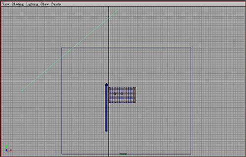
Start by creating a simple nurbs plane. This can be done by selecting Create>Nurbs Primitives>plane. This plane will be used as a surface emitter to generate the rain particles. For this reason rename the plane to Sky. Next, you will need to scale and move the plane to the proper location. With the plane selected, enter the following values in the channel box:
You will now noticed that the plane has been scaled and positioned above the flag. |
|
Step 9: Edit the Rain Particle Attributes
|
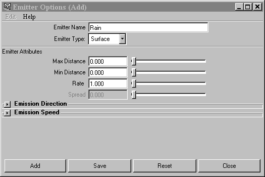
You will now make a surface emitter out of the rain. With the plane selected, select Particles>Emit from object>Options. Under the emitter name enter Rain. Under the emitter type drop-down box, select Surface. After you have filled out the fields, select the Add button to add the emitter. Now with the Particle emitter selected, select Windows>Attribute Editor, to open the particle emitter's attribute editor. In the attribute change, change the following fields to the corresponding values:
|
|
|
You will now need to make a few adjustments to the physical attributes of the rain particles. With the particles selected, open the Attribute Window by selecting Windows>Attribute Editor. Under the render attributes, set the Particle Render Type to Tube(s/w). Next select the button to add attributes for the current render type. This should create three sliders: Radius 0, Radius 1, and Tail Size. Set both the Radii of the Tube attribute, Radius 0 and Radius 1, to be 0.05. You will now create an expression for the Tail Size of the particles. In the box next to Tail Size, right click and select the Expression Editor. Set the tail size of the rain to be a random function between 0.3 and 1, using the rand function. In the expression editor, enter the following line: particleShape1.tailSize = rand(0.3, 1); In the Add Dynamic Attributes section, Click the LifeSpan button, and select the checkbox to add a Per Particle Attribute. This will determine the amount of time the particles will travel before they die out. Again we will create an expression for the lifespan. In the Per Particle (Array) Attributes, right click in the lifespanPP box, and select the expression editor. In the expression editor, enter the following line particleShape1. lifespanPP = rand(3,4); This will assign the lifespan of the particle to be a random value between 3 and 4. Now playback the animation. You should see rain particles being emitted from the plane toward the ground. |
|

Step 10: Create a particle shading group and attach it to the Rain particles
|
Now it is necessary to create a new shading group, and assign that to the rain particles to give them the correct color and glow properties. First open the Multilister Window by selecting Windows>Rendering Editors>Multilister. In the MultiLister, create a new Particle Shading Group (Edit > Create > Volumetric Materials; the new group will be listed in the materials section of the MultiLister), select Particle Cloud and name the ShadingGroup particleRainSG. Open the Attribute Editor for particleRainSG by double-clicking on the shader icon in the MultiLister Window. Set the Color Attribute of the shading group with RGB values of 0.73, 0.895, and 1.0. Next map the Transparency attribute of the shading group with a ramp texture. Set the ramp texture with the following values:
Finally, set the Noise to 1.0 and the Noise Frequency to 0.15. Now that the shader is complete, assign it to the Rain Particles. |
|

Step 11: Set the initial state for the dynamic simulation
|
When you playback the animation at this point you will see that the flag is now fluttering in the wind. Go to a frame where the forces have evened out and in the menu go to Solvers > Initial State > Set for all dynamic. You now avoid the first couple frames where the forces need to start up.
|
|
