Modeler is a program that views a 3d hierarchical model, and lets you manipulate joint angles. It also allows you to load different shaders to shade the 3d model, and manipulate the lighting conditions. Modeler is the basis for the Animator program in Project 4, which just extends the functionality of it.
This project is divided into four parts that span the concepts of creating 3d surfaces, surface normals, texturemapping, hierarchical modeling, and shading. There is one requirement for each part:
First, check out theseamazing shaders for inspiration! Head on over to the GLSL tutorials for a really good walkthrough of how to get started on shaders.
Before creating your hierarchical model, you might want to take a look at the matrices section on the help page. The link there also contains a thorough explanation of OpenGL matrices.
Surface of Revolution
In OpenGL, all scenes are made of primitives like points, lines, triangles and quadrilaterals. In this project, you will implement a surface of revolution using glDrawElements with GL_TRIANGLES to make a 3D surfaces. For each mesh, you send a list of vertices (the points that make up the primitive) with normals and texture coordinates, and an array indices specifying triangles. A simple example can be found in the help slides (link is on the right).
Surface Normals
Surface normals are perpendicular to the plane that's tangent to a surface at a given vertex. Surface normals are used for lighting calculations, because they help determine how light reflects off of a surface. Each normal is sent by calling glNormal3f(x, y, z) before the call to glVertex3f(), much like texture mapping.
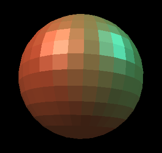
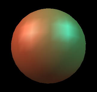
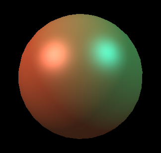
In OpenGL, we often want to approximate smooth shapes like spheres and cylinders using only triangles and quadrilaterals. One way to make the lighting look smooth is to use the normals from the shape we're trying to approximate, rather than just making them perpendicular to the polygons we draw. This means we calculate the normals for each vertex (per-vertex normals), rather than each face (per-face) normals. Shaders allow us to get even smoother lighting, calculating the normals at each pixel. You can compare these methods below:
Per-face
Per-vertex
Per-pixel
Texture Mapping
Texture mapping allows you to "wrap" images around your model by mapping points on an image (called a texture) to vertices on your model. For each vertex, you indicate the coordinate that vertex should apply to, using the command glTexCoord2f(s, t), where s is the X-coordinate and t is the Y-coordinate of the point on the texture that should line up with the vertex. You call glTexCoord2f() right before the vertex you want to apply it to:
When you want to use a texture, you'll need to do the following:
Add a Texture2D field to your model class
In your model class's load() method, call the field's load() method
class MyModel : public Model {
    Texture2D checkers;
    public:
        // Constructor for MyModel
        MyModel() :
        checkers("checkers.png")
        {
        }

        // Your load method
        void load() {
        checkers.load();
        }

        // Your draw method
        void draw() {
        // all geometry after this point will have the checkers texture
        checkers.use();
        }
};

// If you want to get the texture's ID for more advanced stuff:
GLuint textureID = texture.getID();

// If you want to use another texture, just call that texture object's .use() method. To stop using textures, call:
glBindTexture(GL_TEXTURE_2D, 0);
The Hierarchical Model
A hierarchical model is a way of grouping together shapes and attributes to form a complex object. Parts of the object are positioned relative to each other instead of the world. Think of each object as a tree, with nodes decreasing in complexity as you move from root to leaf. Each node can be treated as a single object, so that when you modify a node you end up modifying all its children together. Hierarchical modeling is a very common way to structure 3D scenes and objects, and is found in many other contexts. If hierarchical modeling is unclear to you, you are encouraged to look at the Hierarchical Modeling lecture notes.
Making a Model
You will want to make a model to draw your character, by extending the Model class in model.h:
class MyModel : public Model {
    public:
        // Constructor for MyModel
        MyModel() {
        }

        // Draws the model onscreen
        void draw() {
            // ... call your drawing functions here ...
        }
};
The easiest way to get started is to just modify the existing Scene class in sample.cpp. It extends Model, and in the main() method at the bottom, an instance of it is given to ModelerUserInterface to be displayed onscreen. Later on, you can create your own Model subclass and add it to the Scene class, much like the PointLight and DirectionalLight Models are added. See sample.cpp for details.
Adding Properties To Your Model
A property is an aspect of your model that the user can control. Modeler represents different types of properties with Property classes in model.h:
RangeProperty stores a single number that's within a continuous range.
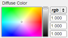
RGBProperty stores a color's red, green, and blue components. Modeler lets you set it with a color picker.
BooleanProperty is either true or false. Modeler lets you set it with a checkbox, making it useful for showing or hiding parts of your model.
ChoiceProperty has an integer value from 0 to N - 1, where N is the number of choices it has. You can assign names to each choice, and Modeler will show the names in the control panel.
To add a property to your model class, do the following:
class MyModel : public Model {
    // Make sure protected: comes before properties, unless you want to be able
    // to access them from other classes (in that case, use public:).
    protected:
    // Add the property here:
        RangeProperty height;
    public:
        // Put constructor here, after the colon
        MyModel() : height("Height", 0.0f, 10.0f, 0.0f, 0.1f) {
            // Add the property to the model's GroupProperty,
            // which is a group of properties that's a property of every Model.
            properties.add(&height);
        }

        void draw() {
            // Use your new property's value for something:
            glScalef(0, height.getValue(), 0);
        }
};
Now, when you open Modeler, a control for your property appears on the left panel.
For further details on each property class, look in model.h. To see how they are added to models, look at the skeleton code's sample model in sample.cpp.
Warning: If you try to set the value of a property of your model by calling setValue(), setRed(), etc., the slider, color picker, or checkbox corresponding to that property will not be updated to show that property's new value. This problem is an oversight in the design of the new Modeler, but will not prevent you from completing the project requirements. If you find yourself needing to set your model's properties, consult your TA's, because you might not be using the Model class the way it was intended to be used.
Affine Transformations in OpenGL
The graphics primitives you have (box, sphere, and cylinder) only accept parameters that define their dimensions. That means you can draw a box, sphere, or cylinder of any size, but it will always be at the origin with the same orientation. What if you want to move it somewhere else, or rotate it to a different orientation -- and you can't edit the primitive's drawing code?
In OpenGL, every vertex is multipled by the modelview matrix, then by the projection matrix:
Modelview Matrix - transforms a point into eye / camera space, where the camera's eye is at the origin, looking down the -z axis, with its up-vector aligned with the +y axis.
Projection Matrix - transforms a point from eye / camera space into normalized device space, which is a 2D plane that represents your screen surface. Its coordinates go from -1 to 1 on each axis, and conversion to pixels is done depending on the size of your OpenGL window.
Since Modeler takes care of projection, you'll modify the modelview matrix. OpenGL has several functions that create matrices for common transformations, then multiply them by the modelview matrix:
glRotatef(degrees, x, y, z)
Rotates all vertices by degrees degrees around a line with slope vector <x, y, z> that passes through the origin. Use the right-hand rule with the vector to determine the direction of rotation.
glTranslatef(x, y, z)
Add <x, y, z> to all vertices.
glScalef(x, y, z)
Multiplies all vertices by <x, y, z>, producing a scaling effect relative to the origin.
If you called glTranslatef(1, 0, 0), then called glutSolidSphere(1, divisions, divisions), the sphere would be drawn centered around (1, 0, 0) because all of its vertices had 1 added to their X-coordinates. Each transformation has the effect of creating a "model space" with its own origin and axes. The sphere was drawn at the origin of a model space created by glTranslatef(1, 0, 0).
Hierarchical Transformations in OpenGL
Once you have applied a transformation to the modelview matrix, it will be applied to every point sent to the graphics card forever! To undo the transformation, you need to remember the matrix's contents.
glPushMatrix()
use this function to push the current modelview matrix onto OpenGL's internal stack.
glPopMatrix()
then use this function to pop the last pushed matrix off that stack and copy it into the modelview matrix.
Make sure you match each glPushMatrix() with a corresponding glPopMatrix(), so that your modelview matrix is returned to its original state. This makes it easy to "nest" your transformations:
// Here, modelview matrix is in world space
glPushMatrix(); // save world space matrix
    // Still in world space
    glTranslate(1, 0, 0);
    // Now in model space (everything translated left by 1).
    glutSolidSphere(1, divisions, divisions);

    // Here's a "nested" transformation.  After the corresponding glPopMatrix(),
    // we'll be back in model space.
    glPushMatrix(); // save model space matrix
        // Still in model space
        glTranslate(3, 0, 0)
        // Now in "model space 2"
        glutSolidSphere(1, divisions, divisions);
        glPopMatrix(); // copy model space matrix into modelview matrix
    // Back in model space
glPopMatrix(); // copy world space matrix into modelview matrix
// Back in world space
Blinn-Phong Shader
A shader is a program that controls the behavior of a piece of the graphics pipeline on your graphics card.
Geometry shaders can turn a single point into multiple points. They are useful for advanced modeling, e.g., refining a coarse triangle mesh into a smooth surface with many triangles, but require very recent graphics hardware and are not part of the core requirements of this project.
Vertex shaders are run once for each vertex in your model. They transform it into device space (by applying the modelview and projection matrices), and determine what each vertex's properties are.
Fragment (or pixel) shaders are run once for every pixel to determine its color.
Shaders determine how the scene lighting affects the coloring of 3D surfaces. In OpenGL, there are two basic kinds of lights:
Point Light - a light that is emitted from a point in world space. The intensity of the light is attenuated (reduced) based on how far it travels from this point. In the physical world, the intensity of a point light decreases with the square of the distance. We can model this with quadratic distance attenuation: dividing the intensity by some function a*r^2+b*r+c, where r is the distance from the light source and a, b, and c are chosen arbitrarily.
Directional Light - a light that always hits a surface from a certain direction, no matter where it is. It has no attenuation.
A shading model determines how the final color of a surface is calculated from a scene's light sources and the object's material. We have provided a shader that uses the Blinn-Phong shading model for scenes with directional lights. See lecture notes for details on the Blinn-Phong shading model.
Tips for Using the Sample Shaders
Ashikhmin Anisotropic Shader
This shader uses the Ashikhmin-Shirley lighting model to produce an anisotropic reflection effect. To see the effect, try setting either the Anisotropic X or Anisotropic Y slider close to 0 (0.1), and scale up the other one to see highlighting in different tangent vector directions, then move the camera around the object.
Ward Anisotropic Shader
This shader uses the Ward lighting model to produce an anisotropic reflection effect. Again, to see the effect, try setting either the Anisotropic X or Anisotropic Y slider close to 0 (0.1), and scale up the other one to see highlighting in different tangent vector directions, then move the camera around the object. Additionally, manipulating the "shininess" factor will affect this shader. Manipulate the In(Specular Exponent) slider to see this change.
Schlick Shader
This shader uses the Schlick approximation to the Fresnel term of the specular reflection. The Schlick N1 and Schlick N2 sliders control factors that simulate indices of refraction, with 1 being the index of refraction of a vacuum, and very close to that of air. To see a change in specular highlighting, try setting one of the sliders near 1 and scaling up the other. When the sliders are roughly equal to each other, there will not be much of a highlight (i.e. light doesn't refract much when passing from air to air).
Diffraction Shader
This shader implements a diffraction effect. To see it in action, select a Diffraction Color (convenience of labeling - it is a color that will permeate the object similar to diffuse or specular), then spin the camera around the object to see the diffraction effect.
Additional Shaders
These are additional shader ideas that you can create. You are required to create another shader(s) worth at least 3 whistles (or 1.5 bells). Additional bells or whistles are extra credit.
You can use the sample solution Modeler to develop some of these shaders, but others require texture maps to be provided -- which the sample solution may not provide to your shader.
Look below for instructions on how to use these in your model
Spot Light Shader
Create a shader that supports a spot light source, and add a third light source to your Modeler. We should be able to adjust the spot light parameters via sliders.
Cartoon Shader
Create a shader that produces a cartoon effect by drawing a limited set of colors and a simple darkening of sillouettes for curved objects based on normal and viewing direction at a pixel. This per-pixel silhouette-darkening approach will work well in some cases around curved surfaces, but not all. For more extra credit, get it to work well for all shapes and with a fixed silhouette thickness.
Schlick Shader
Create a shader, and sliders to control it, thatnuses the Schlick approximation to approximate the contribution of the Fresnel factor to the specular reflection of light.
Blinn-Phong and Texture Mapping Shader
Extend your Blinn-Phong shader to support texture mapping. Remember to keep a copy of your original Blinn-Phong shader for grading.
Blinn-Phong and Mipmapped Texture Mapping Shader
Extend your Blinn-Phong shader to support Texture Mapping and (optionally) controllable mipmap levels. If mipmapping, you should have at least three mipmap levels, and you should change the mipmap level dynamically based on the distance of the textured object from the camera. Remember to keep a copy of your original Blinn-Phong shader for grading. Note: Texture mapping earns a bell of credit; an additional whistle is awarded for mipmapping.
Tessellated Procedural Shader
Make a shader that produces an interesting, repeating pattern, such as a brick pattern, without using a texture.
Bump Mapping Shader
This shader uses a texture to perturb the surface normals of a surface to create the illusion of tiny bumps, without introducing additional geometry.
Diffraction Shader
Create a shader that produces a diffraction effect when you move around the object.
x2
Anisotropic Shader
Create a shader that produces anisotropic specular highlighting, creating a shiny metal appearance. Additionally, add sliders to control the magnitude in 2 perpendicular directions.
x2
Environment Mapped Shader
To make an object appear really shiny (i.e. metallic), it needs to reflect the objects around it. One way to do this is to take a panoramic picture of the surroundings, store it in a texture, and use that texture to determine what should be reflected. For simplicity, we recommend obtaining an existing environment map from somewhere (perhaps making it yourself with a 3D raytracer).
x3
Cloud / Noise Shader
Create a shader that uses noise functions (like Perlin noise) to generate clouds. You may not use textures for this shader. Credit depends on the realism of the clouds.
Using Shaders In Your Model
Shader files are loaded, compiled, and linked by ShaderProgram objects. If you want to add a shader:
Add a ShaderProgram field to your model.
Call its constructor after the colon for your model's constructor.
The ShaderProgram constructor takes three filenames:
Vertex shader
Pixel shader
Geometry shader (omit this parameter unless you actually have one)
class MyModel : public Model {
public:
    Texture2D texture;
    ShaderProgram shader;

    // Your model constructor.
    // The constructors for your shaders, textures,
    // and properties go after the color.
    MyModel() : texture("checkers.png"), shader("shader.vert", "shader.frag") {v
        // ...
    }
};

// Now, if you made a ShaderProgram field called shader, you could use that shader in your draw() method like this:
shader.use();   // This shader will be applied to all subsequent geometry.

// If you want to use another shader, just call that shader object's use() method. To stop using shaders, call:
glUseProgram(0);

// If you want to get the shader program's ID for more advanced stuff:
GLuint shaderProgramID = shader.getID();
Tip: If you have an error in your shader code, you do not have to restart modeler. Instead, fix your shader, then go to File->Reload Textures And Shaders.
Important: Like the rest of your Modeler binary, your shaders must work on the lab machines. If your code complies with the GLSL standard, it should work fine. One way you can verify that your code is compliant with the GLSL standard is to install the GLSL Validator tool. A good alternative tool is the glslang reference compiler. However, please still test on the lab machines.
Requirements
Surface of Revolution
Write code to create a 3D surface in the drawRevolution() method in modelerdraw.cpp. Your shape must:
have appropriate texture coordinates for each vertex;
have appropriate per-vertex normals;
have surfaces drawn using only glDrawElements with GL_TRIANGLES as its primitive type input;
use the divisions variable that already exists in drawRevolution() to determine how many bands your surface is sliced into.
Hierarchical Model
You must come up with a character that meets these requirements:
Uses glTranslate(), glRotate(), and glScale() in meaningful ways.
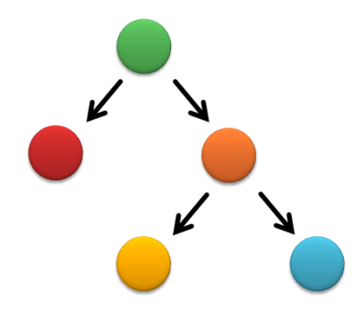
Has at least two levels of branching - There must be at least two instances in your model where you draw something, save the current matrix, apply an affine transformation such as glTranslate(), glRotate(), and glScale(), draw something else, then return to your previous matrix, apply a new transformation, and draw something else. You must also use glPushMatrix() and glPopMatrix() to nest your matrix transformations (see below for details). Here's a pseudocode example of a minimal solution, along with a scene graph:
draw geometry
push matrix
    translate up
    draw geometry

    push matrix
        translate left
        draw geometry
    pop matrix

    push matrix
        translate right
        draw geometry
    pop matrix
pop matrix
push matrix
    translate down
    draw geometry
pop matrix
Has at least 1 multiple-joint slider that controls multiple joints or components of your model. For example, you might have your character waving, which would require that you control the shoulder and elbow joints simultaneously.
Point Light Blinn-Phong Shader
Add support for the scene's point light, by editing the files shader.vert and shader.frag. You need to include quadratic distance attenuation. Please open these files and read the comments for details. Hint: you may not have to edit on of these files.
gl_LightSource[1].position stores the point light's position.
gl_FrontLightProduct[1] is a structure that contains the material properties of the object (ambient, specular, and diffuse colors) multiplied by the point light's ambient, specular and diffuse colors.
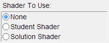
We have provided the sample solution modeler_solution.exe in your repository, which lets you compare your shader to the (correct) sample solution shader. To choose which shader to show, click on "Scene" and click the radio button for the shader you want to use. The sample solution also contains both a point light and a directional light for you to manipulate. Click the "Point Light" or "Directional Light" on the list in the top left corner to edit a light's properties or move it around. The difference feature in the sample solution will compare your shader to the solution shader for you. To use it, select "Difference" under "Shader To Use." Any differences between your shader and the solution shader will become highlighted in the display window. Differences are highlighed by color channel, so if the red is different, then you'll see a bright red pixel, if the green is different, you'll see a bright green pixel, etc. If there are no differences between the two shaders, the entire image should appear black. If there are a few thin highlights along the edges, that is ok since it is probably due to differences in rounding and you will not be counted off for it in grading.
Create an Additional Shader
Create another shader(s) from the list above that is worth at least 3 whistles (or 1.5 bells). This is required and will not count as extra credit. However, any additional bells or whistles will be considered extra credit. You must keep your point light Blinn-Phong shader separate, so we can grade it separately, and you must exhibit this shader in your Modeler binary. Consult OpenGL Shading Language, "the orange book" for some excellent tips on shaders. Ask your TA's if you would like to implement a shader that isn't listed above. Credit for any shader may be adjusted depending on the quality of the implementation, but any reasonable effort should at least earn you the required whistle.
Turn-in Information
Please follow the general instructions here. More details below:
Project Submission
Make sure you include all of your shader files. The Point Light Blinn-Phong Shader files should be named shader.frag and shader.vert so we can load them into the sample solution and compare. You may name your other shaders as you like, but we recommend that the fragment shaders end in .frag and the vertex shaders end in .vert.
Also make sure to copy over any textures or anything that is needed.
Artifact Submission
The modeler application itself is the artifact. To submit it, you will need to do a few special steps you didn't need to do for the binary submission. Basically, you'll encrypt your Modeler shaders and embed them in your program.
You will turn in one artifact per group
Make sure your shaders are compliant with the GLSL standard, by checking them with the GLSL Validator tool. Otherwise, some people might not be able to run your artifact.
Build your Modeler application in Debug mode.
Run your Modeler application. On its File menu, click Generate shaders.cpp. This will bundle all your shaders into a file named shaders.cpp, which was previously empty. It also encrypts your shaders, making it more difficult for future students to steal your hard work.
Recompile your application in Release mode. This will cause shaders.cpp to be included in your binary, and in Release mode, the Generate shaders.cpp menu option will be hidden. If you don't compile in Release mode, many people may not be able to run your artifact. Also, we may take down your submission at the end of the quarter (since future students could generate their shaders.cpp files from your submission).
Create a zip file containing only your Modeler application, its textures, and any other files it needs to run. Do not include shaders, as they were "built into" your Modeler binary file when you compiled it with shaders.cpp.
Extract your zip file to your desktop, and make sure that you can run Modeler (i.e. you aren't missing any files, and the most recent versions of your shaders are being used).
Take a screenshot using File->Save Image... from inside your app.
Turn in your screenshot, zip file, and any comments or directions on how to use your Modeler to the artifact upload page.
Note: If Modeler generates a broken shaders.cpp file, you can undo the change by replacing the contents of shaders.cpp with:
Bells and whistles are extra extensions that are not required, and will be worth extra credit. You are also encouraged to come up with your own extensions for the project. Run your ideas by the TAs or Instructor, and we'll let you know if you'll be awarded extra credit for them. If you do decide to do something out of the ordinary (that is not listed here), be sure to mention it in a readme.txt when you submit the project.
Come up with another whistle and implement it. A whistle is something that extends the use of one of the things you are already doing. It is part of the basic model construction, but extended or cloned and modified in an interesting way. Ask your TAs to make sure this whistle is valid.
Add some widgets that control adjustable parameters to your model so that you can create individual-looking instances of your character. Try to make these actually different individuals, not just "the red guy" and "the blue guy."
Drawing all of the normals (as small lines, perhaps) can be extremely useful for debugging issues related to face directions. Add a feature to visualize the normals for your surface of revolution, which can be toggled on and off in the menu.
Implement the "Hitchcock Effect" described in class, where the camera zooms in on an object, whilst at the same time pulling away from it (the effect can also be reversed--zoom out and pull in). The transformation should fix one plane in the scene--show this plane. Make sure that the effect is dramatic--adding an interesting background will help, otherwise it can be really difficult to tell if it's being done correctly.
Build a complex shape as a set of polygonal faces, using triangles (either the provided primitive or straight OpenGL triangles) to render it. Examples of things that don't count as complex: a pentagon, a square, a circle. Examples of what does count: dodecahedron, 2D function plot (z = sin(x2 + y)), etc. Note that using the dodecahedron primitive (or other primitives apart from triangles) does not meet this requirement.
On the Modeler menu bar, there is an Animate menu. When you click it and check the "Enable" box, your model's tick() method will get called about 24 times per second, and its draw() method will be called at least that often. The rate is controlled by the variable framesPerSecond in modelerui.cpp. You can use this fact to implement an animation. You can keep track of time by incrementing a counter every time your tick() method is called.
A display list is a "recording" of OpenGL calls that gets stored on the graphics card. Thus, display lists allow you to render complicated polygons much more quickly because you only have to tell the graphics card to replay the list of commands instead of sending them across the (slow) computer bus. A display list tutorial can be found here. Implement a display list to draw one of your models (e.g., the surface of revolution) and demonstrate the difference in performance when you have extremely complicated geometry/lots of polygons.
Implement a smooth curve functionality. Examples of smooth curves are here. These curves are a great way to lead into swept surfaces (see below). Functional curves will need to be demonstrated in some way. One great example would be to draw some polynomial across a curve that you define. Students who implement swept surfaces will not be given a bell for smooth curves. That bell will be included in the swept surfaces bell. Smooth curves will be an important part of the animator project, so this will give you a leg up on that.
Implement one or more non-linear transformations applied to a triangle mesh. This entails creating at least one function that is applied across a mesh with specified parameters. For example, you could generate a triangulated sphere and apply a function to a sphere at a specified point that modifies the mesh based on the distance of each point from a given axis or origin. Credit varies depending on the complexity of the transformation(s) and/or whether you provide user controls (e.g., sliders) to modify parameters.
Heightfields are great ways to build complicated looking maps and terrains pretty easily. Implement a heightfield to generate terrain in an interesting way. You might try generating fractals, or loading a heightfield from an image (i.e., allowing the user to design the height of the terrain by painting the image in an image editor and importing it).
x2
Add a function in your model file for drawing a new type of primitive. The following examples will definitely garner two bells; if you come up with your own primitive, you will be awarded one or two bells based on its coolness. Here are three examples:
Surfaces of rotation - given a curve and an axis, draw the surface that results from sweeping the curve around the axis. This is really nice for making pottery :).
Rail surfaces - see Watt, p. 41.
Swept surfaces (this is worth 3 bells) -- given two curves, sweep one profile curve along the path defined by the other. These are also known as "generalized cylinders" when the profile curve is closed. This isn't quite as simple as it may first sound, as it requires the profile curve to change its orientation as it sweeps over the path curve. See this page for some uses of generalized cylinders. This document may be helpful as well, or see the parametric surfaces lecture from a previous offering of this class.
x2
(Variable) Use some sort of procedural modeling (such as an L-system) to generate all or part of your character. Have parameters of the procedural modeler controllable by the user via control widgets. In a previous quarter, one group generated these awesome results.
x2
In addition to mood cycling, have your character react differently to UI controls depending on what mood they are in. Again, there is some weight in this item because the character reactions are supposed to make sense in a story telling way. Think about the mood that the character is in, think about the things that you might want the character to do, and then provide a means for expressing and controlling those actions.
x3
One difficulty with hierarchical modeling using primitives is the difficulty of building "organic" shapes. It's difficult, for instance, to make a convincing looking human arm because you can't really show the bending of the skin and bulging of the muscle using cylinders and spheres. There has, however, been success in building organic shapes using metaballs. Implement your hierarchical model and "skin" it with metaballs. Hint: look up "marching cubes" and "marching tetrahedra" --these are two commonly used algorithms for volume rendering. For an additional bell, the placement of the metaballs should depend on some sort of interactically controllable hierarchy. Try out a demo application.
Metaball Demos: These demos show the use of metaballs within the modeler framework. The first demo allows you to play around with three metaballs just to see how they interact with one another. The second demo shows an application of metaballs to create a twisting snake-like tube. Both these demos were created using the metaball implementation from a past CSE 457 student's project.
If you have a sufficiently complex model, you'll soon realize what a pain it is to have to play with all the sliders to pose your character correctly. Implement a method of adjusting the joint angles, etc., directly though the viewport. For instance, clicking on the shoulder of a human model might select it and activate a sphere around the joint. Click-dragging the sphere then should rotate the shoulder joint intuitively. For the elbow joint, however, a sphere would be quite unintuitive, as the elbow can only rotate about one axis. For ideas, you may want to play with the Maya 3D modeling/animation package, which is installed on the workstations in 228. Credit depends on quality of implementation.
x4
Another method to build organic shapes is subdivision surfaces. Implement these for use in your model. You may want to visit this to get some starter code.
Monster Bells
Disclaimer: please consult the course staff before spending any serious time on these. These are all quite difficult (I would say monstrous) and may qualify as impossible to finish in the given time. But they're cool.
Inverse kinematics
The hierarchical model that you created is controlled by forward kinematics; that is, the positions of the parts vary as a function of joint angles. More mathematically stated, the positions of the joints are computed as a function of the degrees of freedom (these DOFs are most often rotations). The problem of inverse kinematics is to determine the DOFs of a model to satisfy a set of positional constraints, subject to the DOF constraints of the model (a knee on a human model, for instance, should not bend backwards).
This is a significantly harder problem than forward kinematics. Aside from the complicated math involved, many inverse kinematics problems do not have unique solutions. Imagine a human model, with the feet constrained to the ground. Now we wish to place the hand, say, about five feet off the ground. We need to figure out the value of every joint angle in the body to achieve the desired pose. Clearly, there are an infinite number of solutions. Which one is "best"?
Now imagine that we wish to place the hand 15 feet off the ground. It's fairly unlikely that a realistic human model can do this with its feet still planted on the ground. But inverse kinematics must provide a good solution anyway. How is a good solution defined?
Your solver should be fully general and not rely on your specific model (although you can assume that the degrees of freedom are all rotational). Additionally, you should modify your user interface to allow interactive control of your model though the inverse kinematics solver. The solver should run quickly enough to respond to mouse movement.
If you're interested in implementing this, you will probably want to consult the CSE558 lecture notes.
View-dependent adaptive polygon meshes
The primitives that you are using in your model are all built from simple two dimensional polygons. That's how most everything is handled in the OpenGL graphics world. Everything ends up getting reduced to triangles.
Building a highly detailed polygonal model often requires millions of triangles. This can be a huge burden on the graphics hardware. One approach to alleviating this problem is to draw the model using varying levels of detail. In the modeler application, this can be done by specifying the quality (poor, low, medium, high). This unfortunately is a fairly hacky solution to a more general problem.
First, implement a method for controlling the level of detail of an arbitrary polygonal model. You will probably want to devise some way of representing the model in a file. Ideally, you should not need to load the entire file into memory if you're drawing a low-detail representation.
Now the question arises: how much detail do we need to make a visually nice image? This depends on a lot of factors. Farther objects can be drawn with fewer polygons, since they're smaller on screen. See Hugues Hoppe's work on View-dependent refinement of progressive meshes for some cool demos of this. Implement this or a similar method, making sure that your user interface supplies enough information to demonstrate the benefits of using your method. There are many other criteria to consider that you may want to use, such as lighting and shading (dark objects require less detail than light ones; objects with matte finishes require less detail than shiny objects).
Hierarchical models from polygon meshes
Many 3D models come in the form of static polygon meshes. That is, all the geometry is there, but there is no inherent hierarchy. These models may come from various sources, for instance 3D scans. Implement a system to easily give the model some sort of hierarchical structure. This may be through the user interface, or perhaps by fitting an model with a known hierarchical structure to the polygon mesh (see this for one way you might do this). If you choose to have a manual user interface, it should be very intuitive.
Through your implementation, you should be able to specify how the deformations at the joints should be done. On a model of a human, for instance, a bending elbow should result in the appropriate deformation of the mesh around the elbow (and, if you're really ambitious, some bulging in the biceps).