There were many ways to modify the control and data paths.
Changes to the control and data signals:
ALU inputs (3 points)
Add an extra input to the MUX which feeds the top (A) or bottom (B) input
(either one is OK) of the ALU. This input is the value from the ALUOut register
(not ALU Result - why?). Widen the ALUSrcA or ALUSrcB control lines as
appropriate (if you change the existing order of MUX inputs, be sure to modify
the finite state machine states as well).
Register file inputs (3 points)
Add a new MUX to the Read register 1 input line or Read register 2 input line
(should be Read register 1 if you put the above MUX on the B ALU input or Read
register 2 if you put the MUX on the A ALU input). The inputs of this MUX are
the existing value sent to Read register 1 (or 2) and bits 4 to 0 of the
instruction register. Add a new control line (which I call ReadRegSelect) from
the Control unit to this new MUX.
Changes to the finite state machine:
Assume that we put the new MUX on the Read register 2 input line and thus add the extra ALU MUX input to the A ALU input.
General changes (1 point):
Turn ALUSrcA = 0 into ALUSrcA = 00 and ALUSrcA = 1 into ALUSrcA = 01.
Modify state 1 (1 point):
Add ReadRegSelect = 0.
New states and transitions (6 points):
Transition from state 1 to state P when Op = 'add3'. In state P, ALUSrcA =
01, ALUSrcB = 00, ALUOp = 00 (not 10 - why?) and ReadRegSelect = 1 (reads third
source register value into B register for the following cycle).
Transition from state P to state Q. In state Q, ALUSrcA = 10, ALUSrcB = 00, ALUOp = 00.
Transition from state Q to state 7.
5.24 (4 points total)
average CPI / cycles per second = average execution time per instruction
Machine M1
average CPI = 4 x % ALU + 4 x % stores + 5 x % loads + 3 x % branch + 3 x % jump (assuming jal takes 3 cycles which is probably wrong - see below)
% ALU = 9 + 17 + 1 + 2 + 5 + 2 + 2 + 1 + 1 + 1 + 2 = 43
% stores = 12 + 1 = 13
% loads = 21 + 1 + 1 = 23
% branch = 9 + 8 + 1 + 1 = 19
% jump = 1 + 1 = 2
average CPI = 4 x 43 / 100 + 4 x 13 / 100 + 5 x 23 / 100 + 3 x 19 / 100 + 3 x 2 / 100 = 4.02
average execution time per instruction = 4.02 / (500 x 106) = 8.04 ns
Machine M2
ALU operations now take three cycles and load operations take four cycles.
average CPI = 3 x 43 / 100 + 4 x 13 / 100 + 4 x 23 / 100 + 3 x 19 / 100 + 3 x 2 / 100 = 3.36
average execution time per instruction = 3.36 / (400 x 106) = 8.4 ns
Thus machine M1 is faster than M2. A program with more ALU and/or load operations in the instruction mix could be executed faster on machine M2 than M1.
[There was some ambiguity about whether or not to answer the very last part of the question regarding instruction mix, you didn't lose points for not doing so or answering incorrectly.]
[jal on a multicycle machine would write the register file in a fourth cycle after writing the new PC value. Page 385 of the textbook says that register file accesses are performed in a separate clock cycle. On the other hand the multicycle datapath in the textbook does not have a path for writing the PC to the register file. Also the difference between 3 and 4 cycles for jal has no effect on the relative speeds of M1 and M2.]
5.26 (4 points total)
         beq  $t3, $0,    done
bcpLoop: lw   $t4, 0($t1)
         sw   $t4, 0($t2)
         addi $t1, $t1,   1
         addi $t2, $t2,   1
         addi $t3, $t3,   -1
         bne  $t3, $0,    bcpLoop
done:
6.7 (20 points total)
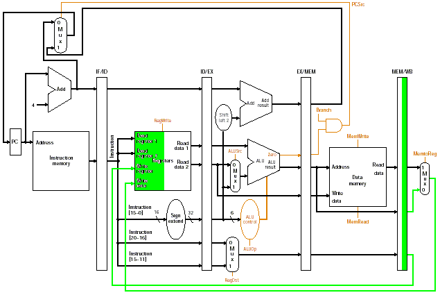
I use green to indicate the active pipeline datapath components in each stage of execution of the add instruction. Uncolored parts are inactive for the add instruction.
Stage 1 (4 points)

Stage 2 (4 points)

Stage 3 (4 points)

Stage 4 (4 points)

Stage 5 (4 points)

6.15 (4 points total)
Dependence diagram (1 point)
There is a dependence line from the lw instruction's MEM/EX pipeline register
to the sub instruction's EX stage.
Pipeline diagram (2 points)
The sub instruction is stalled for one cycle after it enters the ID stage
i.e. the pipeline stages for it look like
IF ID bubble EX MEM WB
Forwarding is required from the MEM/EX pipeline register (from the lw
instruction) to the EX stage (for the sub instruction).
The time taken to execute this code is the time taken between starting the first instruction and finishing the third instruction, which is 8 cycles (1 point).
SMOK problem (4 points)
You should have a DebugInput, 3 labelled registers (Ex, S, SIG) and 3 DebugOutputs. You may use other components too (but should not need to e.g. shifters are not needed for constant shift amounts).